OM-259 Page 14
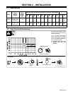
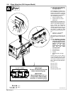
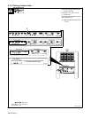
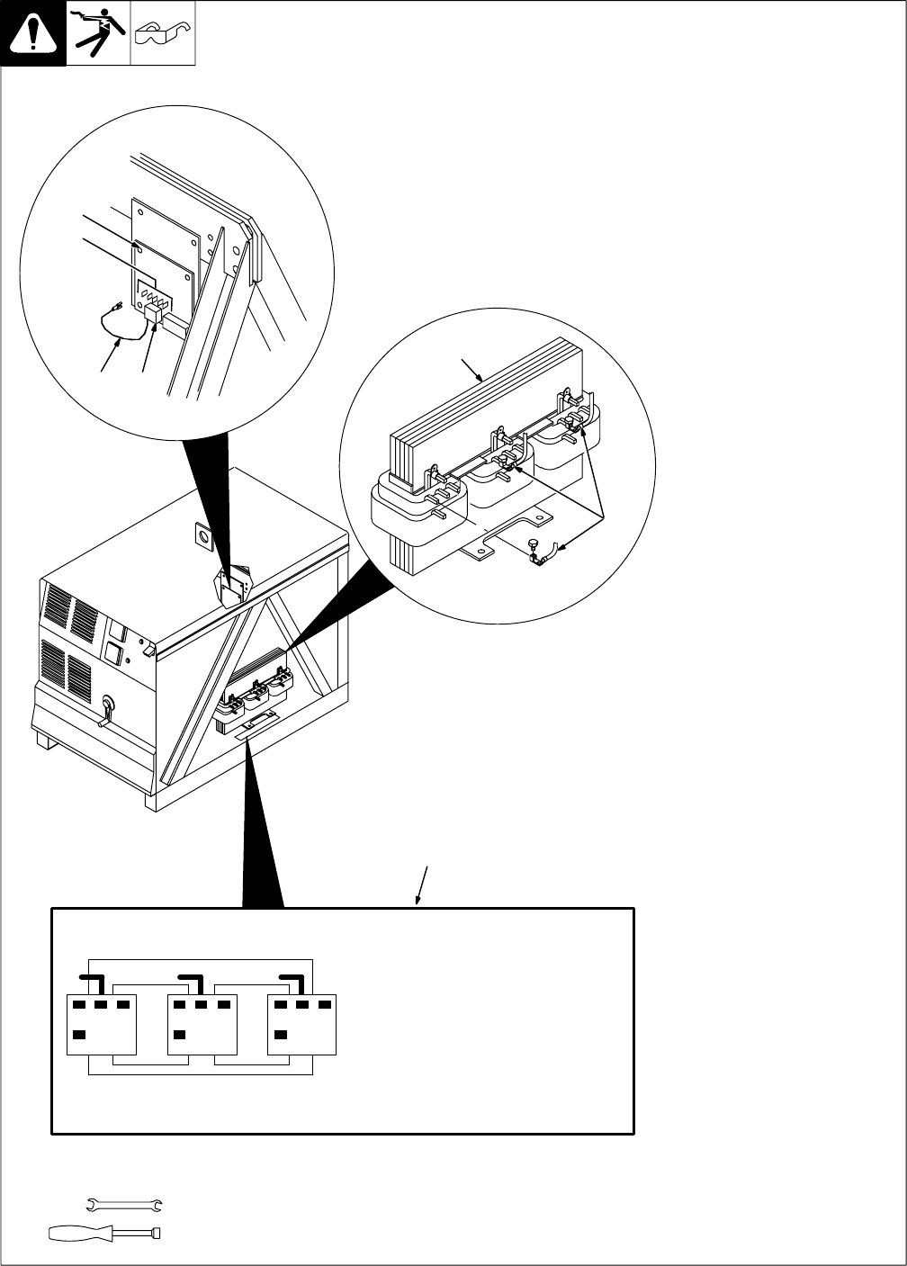
2-8. Slope Selection (250 Ampere Model)
Ref. ST-801 518-A
Y Disconnect and lockout/tag-
out input power before re-
moving side panel.
Lockout/tagging procedures con-
sist of padlocking line disconnect
switch in open position, removing
fuses from fuse box, or shutting off
and red-tagging circuit breaker or
other disconnecting device.
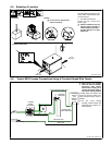
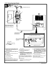
1 Slope Connection Label
2 Tapped Reactor AC-Z And
Slope Coils
Tapped reactor AC-Z is factory con-
nected to slope tap 8 which is suit-
able for most GMAW applications.
AC-Z controls the inductance
applied to the weld current. To
increase inductance and wet out
the weld puddle, connect to a higher
tap number. To stiffen the weld
puddle, connect to a lower tap num-
ber.
3 Leads 70, 71 and 72 With
Pressure Connectors
Slide pressure connectors onto the
same tap of each coil, and secure
them.
Y An unbalanced secondary
current can damage the main
transformer and cause errat-
ic weld conditions. Be sure
leads 70, 71 and 72 are con-
nected to the same
numbered slope turn tap on
each coil. See slope
connection label .
4 Firing Board PC1
5 Receptacle RC2
6 Lead 36
7 Receptacles RC3 Through
RC6
Connect lead 36 from RC2 to
correct receptacle RC4, RC5, RC6
or RC7 to match tap slope connec-
tions made in Section A as follows:
RC3 − 300A (Used With 300A Mod-
els Only)
RC4 for 4 turns
RC5 for 6 turns
RC6 for 8 turns
RC7 for 10 turns.
Reinstall right side panel.
1
2
3
1/2 in
3/8 in
4
7
56
S-177 763-B
864 864 864
000
SLOPE TURNS
TAP SLOPE CONNECTIONS
IMPORTANT:
Be sure connections are clean
before reconnecting tap.
IMPORTANT:
Move friction lug on PC1 to
correct tab to insure proper
operation of voltmeter preset.
10 10 10


