


OM-259 Page 19
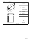
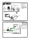
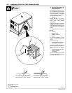
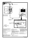
2-15. Connecting Input Power
ST-800 103-B / Ref. ST-801 116
Y Disconnect and lockout/tagout input
power before connecting input con-
ductors from unit.
Y Have only qualified persons make this
installation.
See rating label on unit and check input volt-
age available at site.
1 Line Disconnect Device
2 Input Conductors
3 Grounding Conductor
Select size and length using Section 2-13.
Conductors must comply with national, state,
and local electrical codes. Use lugs of proper
amperage capacity and correct hole size.
4 Strain Relief
Route conductors through strain relief.
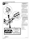
5 Machine Grounding Terminal
6 Line Terminals
Y Make input power connections to the
welding power source before making
connections into a deenergized line
disconnect device.
Connect green or green/yellow grounding con-
ductor to machine grounding terminal first.
Then connect input conductors to line termi-
nals.
Close access door.
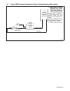
7 Disconnect Device (Supply) Grounding
Terminal
8 Disconnect Device Line Terminals
Y In the deenergized line disconnect de-
vice, connect green or green/yellow
grounding conductor to supply
grounding terminal first, never to a line
terminal. Be sure grounding conductor
goes to an earth ground.
Connect input conductors to line terminals.
9 Overcurrent Protection
Select type and size using Section 2-13 (fused
disconnect switch shown).
Close door on line disconnect device.
3/8 in, 1/2 in
= GND/PE Earth Ground
Tools Needed:
When making connections in
the line disconnect device,
connect the Green Or
Green/Yellow conductor first.
Install conductors into
a deenergized line
disconnect device.
Make connections
to machine first and
supply last.
IMPORTANT
GND/
PE
Connect Green Or Green/Yellow
GND/PE Conductor First.
L1 L2 L3
L1 (U)
L2 (V)
L3 (W)
2
6
3
5
. Tighten nuts to 65 in lb +/- 5 in lb.
4
1
9
8
3
7
3/8 in, 1/2 in