


OM-1582 Page 10
ST-178 794-A
50/60
S/N:
24
10.0
Hz50/60
IP 21
V100 A750 X 100 %
V
U
1
=
A
I
1
=
1
U
2
=
I
2
=
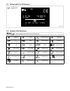
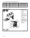
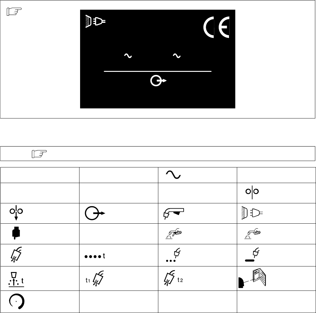
2-2. Rating Label For CE Products
For label location
see Section 4-4.
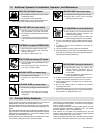
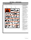
2-3. Symbols And Definitions
Some symbols are found only on CE products.
Note
A
Amperes
V
Volts Alternating Current
X
Duty Cycle
IP
Degree Of
Protection
Hz
Hertz
U
1
Primary Voltage Wire Feed
Jog Output Trigger Line Connection
Press To Set
U
2
Load Voltage Trigger Hold On Trigger Hold Off
Purge Spot Weld Time Spot Weld Continuous Weld
Burnback Time Preflow Time Postflow Time Read Instructions
Increase
I
1
Primary Current
I
2
Rated Current