


OM-2225 Page 12
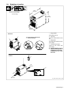
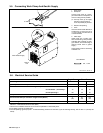
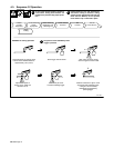
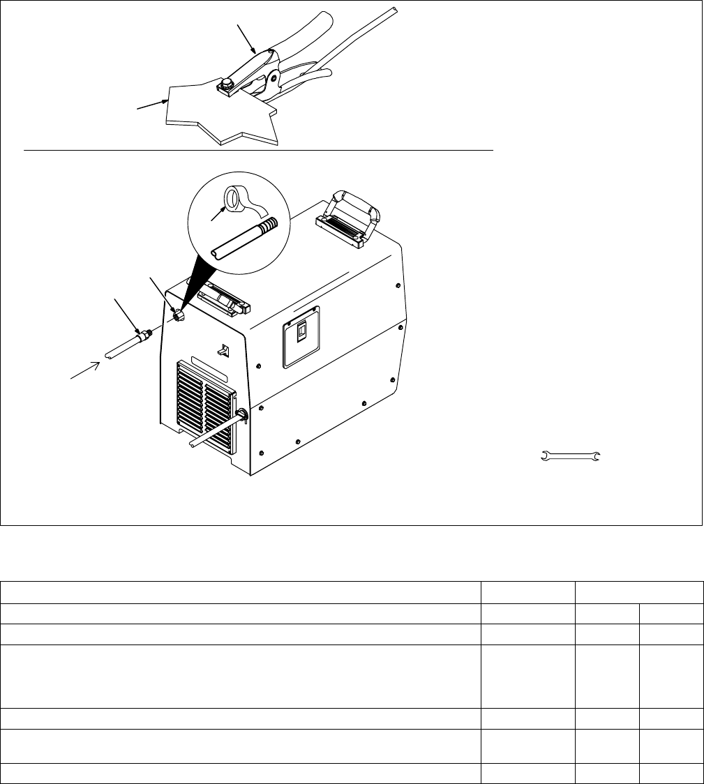
3-5. Connecting Work Clamp And Gas/Air Supply
Ref. 803 640-A / 802 201-B
1 Work Clamp
2 Workpiece
Connect work clamp to a clean,
paint-free location on workpiece, as
close to cutting area as possible.
. Use only clean, dry air supply
with 90 to 150 psi pressure.
Torch requires 80 psi pressure.
3 Gas/Air Inlet Opening
4 Hose
Use hose with an inside diameter of
at least 3/8 in. If hose is over 40 ft
(12.2 m) in length, use hose with 1/2
in inside diameter.
5 Teflon Tape
Obtain hose with 1/4 NPT right-
hand thread fitting. Wrap threads
with teflon tape (optional) or apply
pipe sealant, and install fitting in
opening. Route hose to gas/air
supply.
Adjust gas/air pressure according
to Section 4-2.
Tools Needed:
5/8, 1-1/8 in
From Gas/Air Supply
3
4
5
Rear of
Unit
1
2
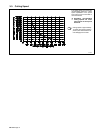
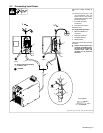
3-6. Electrical Service Guide
Single Phase Three Phase
Input Voltage 230 230 460
Input Amperes At Rated Output 63 35 18
Max Recommended Standard Fuse Rating In Amperes
Circuit Breaker
1
, Time-Delay
2
70 40 20
Normal Operating 3 100 50 25
Min Input Conductor Size In AWG/Kcmil 8 10 14
Max Recommended Input Conductor Length In Feet (Meters)
71
(22)
97
(30)
152
(46)
Min Grounding Conductor Size In AWG/Kcmil 8 10 14
Reference: 1999 National Electrical Code (NEC)
1 Choose a circuit breaker with time-current curves comparable to a Time Delay Fuse.
2 “Time-Delay” fuses are UL class “RK5” .
3 “Normal Operating” (general purpose − no intentional delay) fuses are UL class “K5” (up to and including 60 amp), and UL class “H” ( 65 amp and
above).