


OM-188 414 Page 6
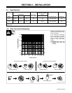
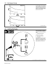
2-3. Volt-Ampere Curves
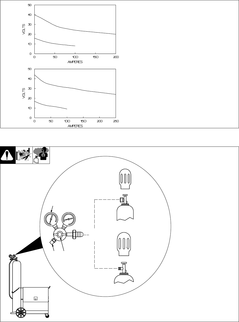
1 Normal Volt-Ampere Curves
The volt-ampere curves show the
normal minimum and maximum
voltage and amperage output capa-
bilities of the welding power source.
Curves of other settings fall be-
tween the curves shown.
Model 201
Model 241
dwg. 802004, 802003
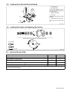
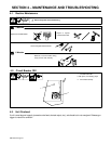
2-4. Installing Gas Supply
Ref. ST-148 265-B / Ref. ST-149 827-B / Ref. ST-158 697-A
2
CO
2
Gas
1
Argon Gas
OR
3
Chain gas cylinder to running gear,
wall, or other stationary support so
cylinder cannot fall and break off
valve.
1 Regulator/Flow Gauge
Install so face is vertical.
2 Gas Hose Connection
3 Flow Adjust
Typical flow rate is 20 cfh (cubic
feet per hour). Check wire man-
ufacturer’s recommended flow
rate. This flow gauge can be
adjusted between 5 and 25 cfh.