


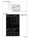
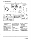

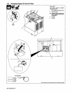
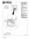

3-2.
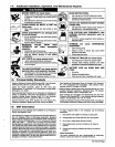
Front
Panel
Controls
8
9
Ret.
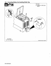
ST-175
920-A
A
Heavy
loading
during
first
50
hours
will
damage
engine.
Keep
load
less
than
225A
(weld)
or
7
kVA
(power)
for
first
50
hours.
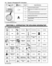
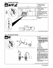
1
Engine
Control
Switch
Si
Use
switch
to
operate
glow
plug
(optional
see
table),
start
engine,
select
speed,
and
stop
engine.
In
Run/Idle
position,
engine
runs
at
idle
speed
at
no
load,
and
weld/power
speed
under
load.
In
Run
position,
engine
runs
at
weld/power
speed.
2
Idle
Lock
Switch
S8
Use
switch
to
lock
engine
in
idle
speed
dur
ing
start-up
(see
table).
Do
not
use
ac
re
ceptacles
with
switch
in
Idle
position.
To
Start:
move
Idle
Lock
switch
to
Idle
posi
tion
and
Engine
Control
switch
to
Start
posi
tion.
Release.
Engine
Control.
switch
.when
engine
starts.
Do
not
crank
engine
while
fly
wheel
is
turning.
Move
Idle
Lock
switch
to
Run/Idle
position
after
engine
warms.
in
arc
starts,
and
reduce
the
chance
of
the
electrode
freezing
in
the
puddle.
Set
at
minimum
for
Tig
welding.
7
Amperage
Control
R4
8
Voltmeter
Vi
(Optional)
10
Remote
Amperage
Control
Switch
S7
Use
switch
to
select
front
panel
or
remote
amperage
control.
11
Remote
Output
(Contactor)
Switch
S6
7
1
2
Using
idle
Lock
Switch
2100
rpm
(No
Load)
3200
rpm
(Load)
3200
rpm
To
Stop:
turn
Engine
Control
switch
to
Stop
9
Ammeter
Al
(Optional)
position.
3
Engine
Hour
Meter
HM
4
Fuel
Gauge
FG
5
Engine
Oil
Pressure
Light
PL1
Engine
stops
and
light
goes
on
If
oil
pres-
Use
switch
to
control
remote
contactor
if
sure
is
too
low,
connected
to
remote
14
receptacle
RC1
-
6
Arc
Force
(Dig)
Control
R5
Use
control
to
automatically
increase
am
perage
as
arc
length
is
decreased,
to
assist
A
Weld
output
terminals
are
energized
when
switch
S6
Is
On
and
engine
Is
running.
OM-l
56368
Page
9