


OM-1500-4 Page 10
SECTION 3 – INSTALLATION
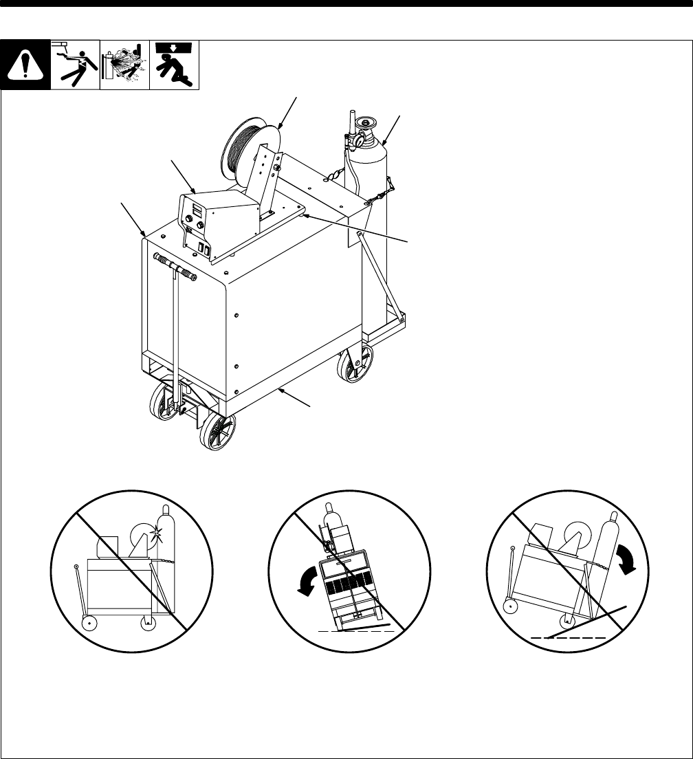
802 806-A
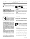
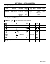
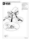
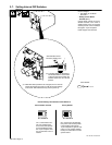
1 Wire Feeder
2 Rubber Feet
Choose slot that allows all rubber
feet to sit securely on top of welding
power source.
3 Wire Spool/Reel
4 Gas Cylinder w/Hose And Re-
gualtor (Customer Supplied)
5 Welding Power Source
6 Running Gear
Y Do not put feeder where
welding wire hits cylinder.
Y Do not move or operate
equipment when it could tip.
1
3
5
4
2
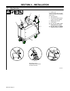
3-1. Site Selection
Wire feeder shown is
representative only and does
not reflect actual unit.
6