


OM-193 084 Page 16
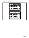
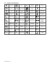
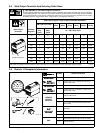
3-5. Weld Output Terminals And Selecting Cable Sizes
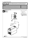
Y ARC WELDING can cause Electromagnetic Interference.
To reduce possible interference, keep weld cables as short as possible, close together, and down low, such as on the floor.
Locate welding operation 100 meters from any sensitive electronic equipment. Be sure this welding machine is installed
and grounded according to this manual. If interference still occurs, the user must take extra measures such as moving
the welding machine, using shielded cables, using line filters, or shielding the work area.
Total Cable (Copper) Length In Weld Circuit Not Exceeding
100 ft (30 m) Or Less
150 ft
(45 m)
200 ft
(60 m)
250 ft
(70 m)
300 ft
(90 m)
350 ft
(105 m)
400 ft
(120 m)
Weld Output
Terminals
Welding
Amperes
10 – 60%
Duty
Cycle
60 – 100%
Duty
Cycle
10 – 100% Duty Cycle
100 4 4 4 3 2 1 1/0 1/0
150 3 3 2 1 1/0 2/0 3/0 3/0
200 3 2 1 1/0 2/0 3/0 4/0 4/0
250 2 1 1/0 2/0 3/0 4/0 2-2/0 2-2/0
300 1 1/0 2/0 3/0 4/0 2-2/0 2-3/0 2-3/0
350 1/0 2/0 3/0 4/0 2-2/0 2-3/0 2-3/0 2-4/0
+
–
400 1/0 2/0 3/0 4/0 2-2/0 2-3/0 2-4/0 2-4/0
–
Output Receptacles
500 2/0 3/0 4/0 2-2/0 2-3/0 2-4/0 3-3/0 3-3/0
600 3/0 4/0 2-2/0 2-3/0 2-4/0 3-3/0 3-4/0 3-4/0
Weld cable size (AWG) is based on either a 4 volts or less drop or a current density of at least 300 circular mils per ampere. S-0007-D
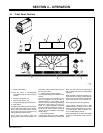
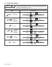
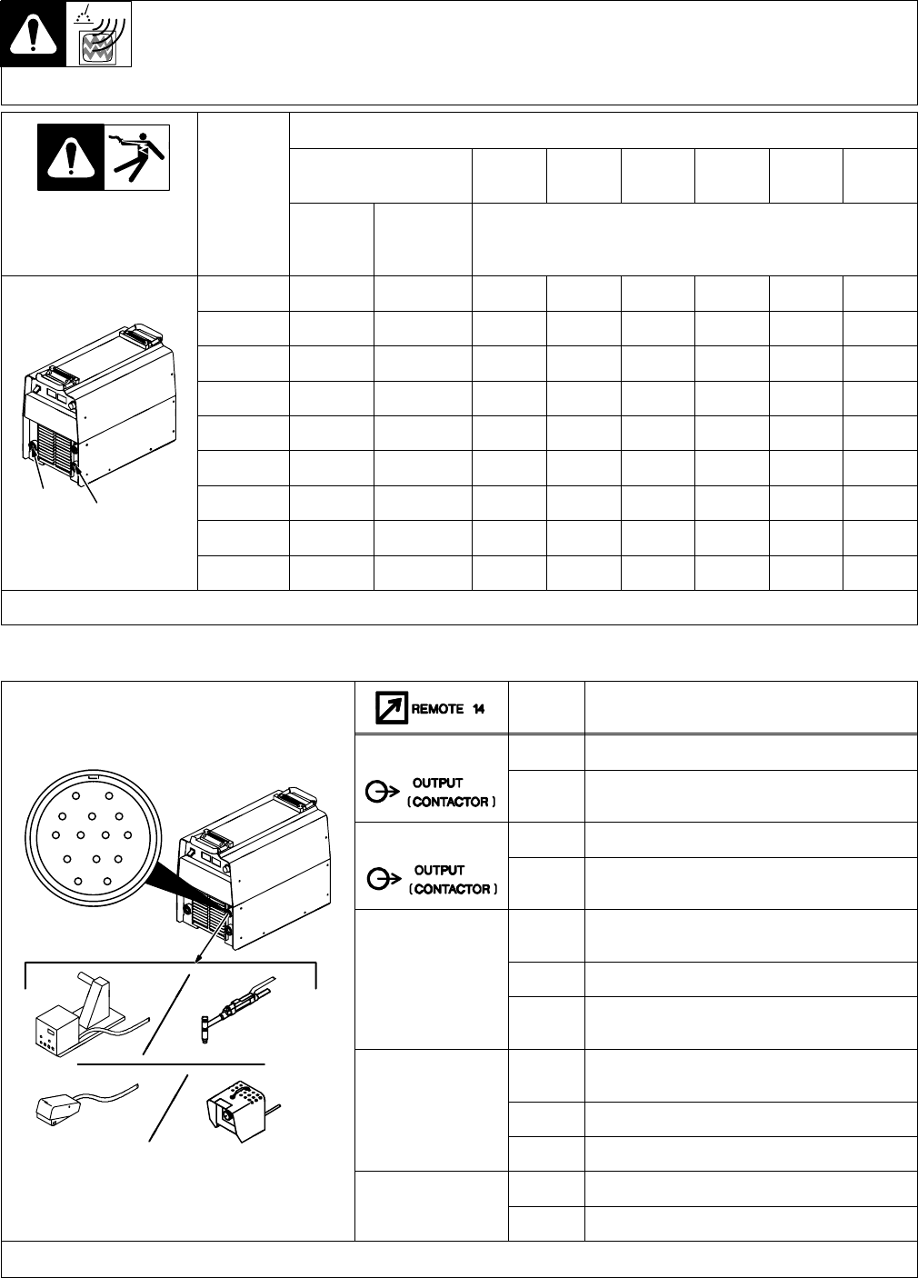
3-6. Remote 14 Receptacle Information
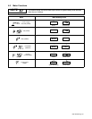
Socket* Socket Information
24 VOLTS AC
A 24 volts ac. Protected by circuit breaker CB2.
AJ
K
I
24 VOLTS AC
B Contact closure to A completes 24 volts ac con-
tactor control circuit.
B
I
C
L
NH
115 VOLTS AC
I 115 volts ac. Protected by circuit breaker CB1.
C
D
M
G
E
F
115 VOLTS AC
J Contact closure to I completes 115 volts ac con-
tactor control circuit.
C Output to remote control; 0 to +10 volts dc, +10
volts dc in MIG mode.
REMOTE
OUTPUT
D Remote control circuit common.
CONTROL
E 0 to +10 volts dc input command signal from re-
mote control.
A/V
H Voltage feedback; +1 volt dc per 10 output recep-
tacle volts.
A/V
AMPERAGE
VOLTAGE
F Current feedback; +1 volt dc per 100 amperes.
ST-801 192
VOLTAGE
M CC/CV select (CC/CV models only).
G Circuit common for 24 and 115 volts ac circuits.
GND
K Chassis common.
*The remaining sockets are not used.