


OM-823 Page 1
SECTION 1 − SAFETY PRECAUTIONS AND SIGNAL WORDS
1-1. GENERAL INFORMATION AND SAFETY
A. General
Information presented in this manual and on various la-
bels, tags, and plates on the unit pertains to equipment
design, installation, operation, maintenance, and
troubleshooting which should be read, understood, and
followed for the safe and effective use of this equipment.
The nameplate of this unit uses international symbols
for labeling the front panel controls. The symbols also
appear at the appropriate section in the text.
B. Safety
The installation, operation, maintenance, and trouble-
shooting of arc welding equipment requires practices
and procedures which ensure personal safety and the
safety of others. Therefore, this equipment is to be in-
stalled, operated, and maintained only by qualified per-
sons in accordance with this manual and all applicable
codes such as, but not limited to, those listed at the end
of Section 1 − Safety Rules For Operation Of Arc Weld-
ing Power Source.
1-2. SAFETY ALERT SYMBOL AND SIGNAL
WORDS
The following safety alert symbol and signal words are
used throughout this manual to call attention to and
identify different levels of hazard and special instruc-
tions.
This safety alert symbol is used with the signal
words WARNING and CAUTION to call atten-
tion to the safety statements.
WARNING statements identify procedures or
practices which must be followed to avoid seri-
ous personal injury or loss of life.
CAUTION statements identify procedures or
practices which must be followed to avoid minor
personal injury or damage to this equipment.
IMPORTANT statements identify special instructions
necessary for the most efficient operation of this equip-
ment.
1-3. DESCRIPTION
Remote Hand Controls are designed for use as remote
amperage or voltage controls in conjunction with a weld-
ing power source or welding generator having electric
control facilities. Remote Hand Controls with the letters
GD displayed in the model description are designed for
use with welding generators only.
SECTION 2 − INSTALLATION
Table 2-1. Cord Conductor Length And Size
Amperage or Voltage Control
Cord Length
Conductor
Size*
No. 16
No. 14
No. 12
No. 14
No. 12
No. 10
Up to 20ft (6 m)
Up to 20ft (6 m) (GD Models)
21 to 100ft (6 to 30 m) (GD Models)
21 to 50ft (6 to 15 m)
51 to 100ft (16 to 31 m)
101 to 200ft (31 to 61 m)
*AWG-American Wire Guage
2-1. LOCATION
The Remote Hand Controls is equipped with a twenty
foot (6 m) interconnecting multi-conductor cord (unless
otherwise specified) which enables the Remote Hand
Control to be remotely located from the welding power
source or welding generator. The Remote Hand Control
can be wall mounted or placed on a stand at the work
area.
If it is necessary to install a muti-conductor cord of long-
er length, refer to Table 2-1 for cord conductor size ac-
cording to the desired length. Refer to Section 5 - Elec-
trical Diagrams for connections
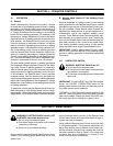
2-2. INTERCONNECTIONS
1. To make connections on models equipped with
the twistlock plug, fully insert the twistlock plug
that is attached to the Remote Hand Control cord
into Remote Amperage or Voltage Control Re-
ceptacle on the welding power source or welding
generator. Turn the cap in a clockwise direction,
as far as it will turn, to lock the connection.
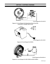
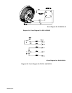
2. To make connections on models equipped with
the 14-pin or 5-pin Amphenol plug, align keyway,
insert plug, and rotate threaded collar fully clock-
wise.