


OM-823G - 2/92
Before unpacking equipment, check carton for any
damage that may have occurred during shipment. File
any claims for loss or damage with the delivering car-
rier. Assistance for filing or settling claims may be ob-
tained from the distributor and/or the equipment manu-
facturer’s Transportation Department.
When requesting information about this equipment, al-
ways provide the Model Description and Serial or Style
Number.
Use the following spaces to record the Model Designa-
tion and Serial or Style Number of your unit. The infor-
mation is located on the rating label or nameplate.
Model
Serial or Style No.
Date of Purchase
RECEIVING-HANDLING
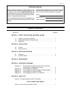
TABLE OF CONTENTS
Section No. Page No.
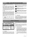
SECTION 1 − SAFETY PRECAUTIONS AND SIGNAL WORDS
1-1. General Information And Safety 1. . . . . . . . . . . . . . . . . . . . . . . . . . . . . . .
1-2. Safety Alert Symbol And Signal Words 1. . . . . . . . . . . . . . . . . . . . . . . . .
1-3. Description 1. . . . . . . . . . . . . . . . . . . . . . . . . . . . . . . . . . . . . . . . . . . . . . . . .
SECTION 2 − INSTALLATION
2-1. Location 1. . . . . . . . . . . . . . . . . . . . . . . . . . . . . . . . . . . . . . . . . . . . . . . . . . . .
2-2. Interconnections 1. . . . . . . . . . . . . . . . . . . . . . . . . . . . . . . . . . . . . . . . . . . . .
SECTION 3 − OPERATOR CONTROLS
3-1. Operation 2. . . . . . . . . . . . . . . . . . . . . . . . . . . . . . . . . . . . . . . . . . . . . . . . . . .
3-2. Contactor Switch 2. . . . . . . . . . . . . . . . . . . . . . . . . . . . . . . . . . . . . . . . . . . .
SECTION 4 − MAINTENANCE
SECTION 5 − ELECTRICAL DIAGRAMS
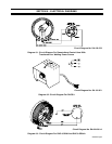
Diagram 5-1. Circuit Diagram For Remote Hand Control Used With
Transformer Arc Welding Power Source 3. . . . . . . . . . . . . . . .
Diagram 5-2. Circuit Diagram For RHCS-3 3. . . . . . . . . . . . . . . . . . . . . . . . . .
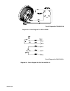
Diagram 5-3. Circuit Diagram For RHC-3-GD9A And RHC-3-GD34A 3. . . .
Diagram 5-4. Circuit Diagram For RHC-3-GD25B 4. . . . . . . . . . . . . . . . . . . .
Diagram 5-5. Circuit Diagram For RHC-14 And RHC-23 4. . . . . . . . . . . . . . .
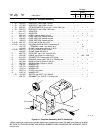
SECTION 6 − PARTS LIST
Figure 6-1. Complete Assembly (RHC-3 Illustrated) 6. . . . . . . . . . . . . . . . . . . . .
LIST OF CHARTS AND TABLES
Table 2-1. Cord Conductor Length And Size 1. . . . . . . . . . . . . . . . . . . . . . . . . . .