


OM-1215 Page 9
SECTION 2 – INSTALLATION
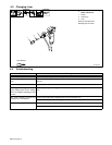
2-1. Specifications
Wire Diameter Range
Approximate
Wire Feed
Range
Cooling
Method
Maximum Spool
Size
Weld Circuit
Rating
Overall
Dimensions
Weight
.030 Thru .047 in
(0.8 Thru 1.2 mm)
Aluminum Wire
.030 Thru 047 in
(0.8 Thru 1.2 mm)
Hard Or Cored Wire
130 To 840 ipm
(4.1 To 20.4
mpm)
Air Cooled
4 in (102 mm)
Diameter
100 Volts, 200
Amperes, 60%
Duty Cycle
Using Argon
Shielding Gas
Length:
11-1/2 in (291 mm)
Width:
2-1/4 in (57 mm)
Height:
8 in (203 mm)
9.1 lb (4.1 kg)
Gun With Cable
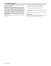
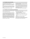
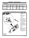
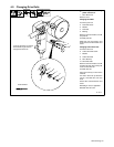
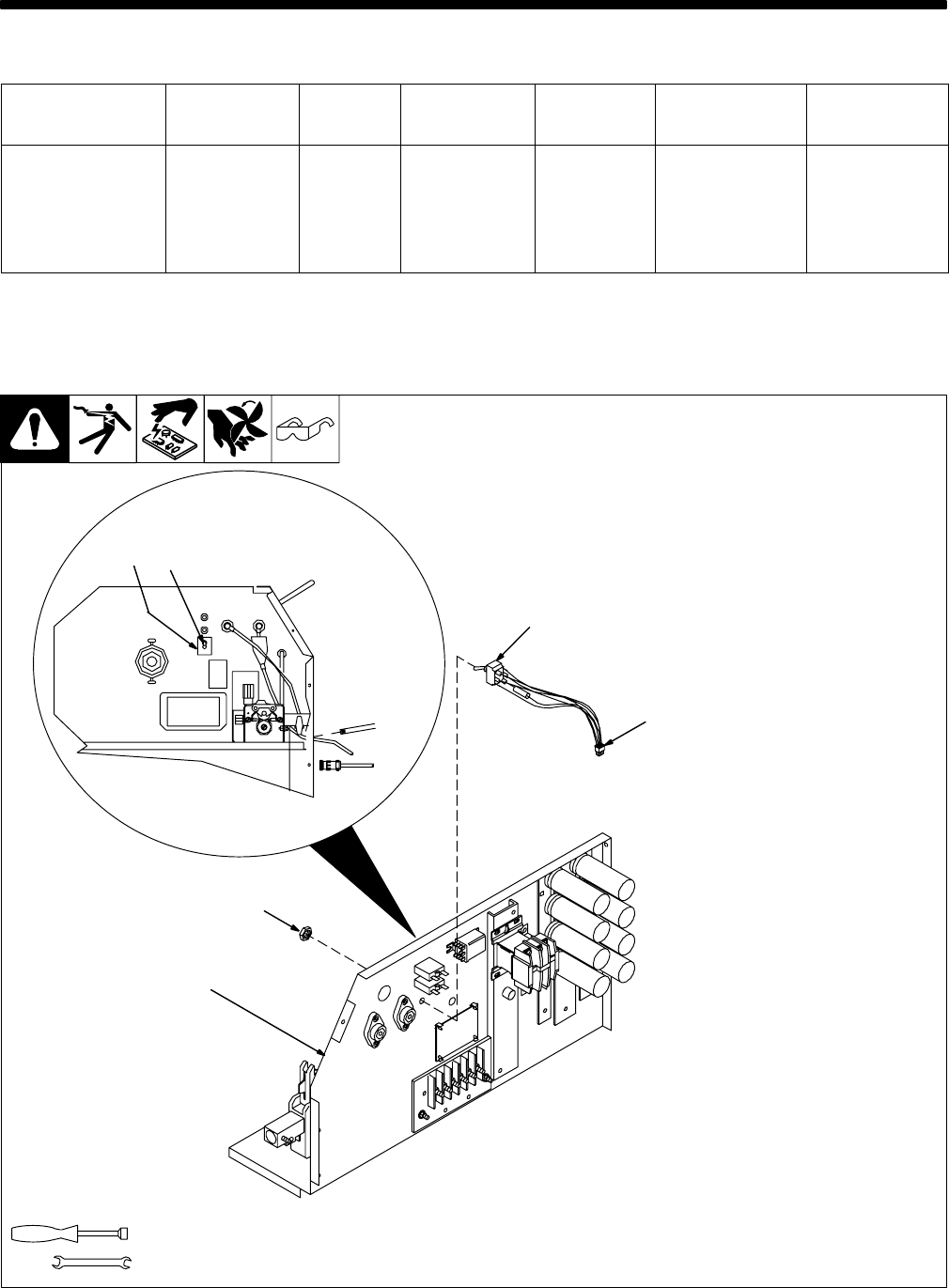
2-2. Installing Spoolgun Switch In Welding Power Source (If Connecting To Millermatic
185 Prior To Serial No. KH376829 Unit Requires Installation Of Field Kit 186871)
802 582
Tools Needed:
3/8 in
9/16 in
2
3
4
5
6
1
Y Turn Off unit, and disconnect
input power.
1 Welding Power Source Center
Baffle
2 Switch Location
Locate plastic plug in center panel.
Remove and discard plug.
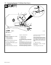
3 Spoolgun Label
4 Spoolgun Switch
5 Jam Nut
Remove top jam nut from switch
(switch is equipped with two nuts, a
jam nut and a backing nut).
Insert switch shaft through center
panel. Switch should be positioned
so lead with resistor is facing down.
Secure switch to center panel with
jam nut. Tighten jam nut enough to
keep switch from rotating.
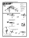
6 Spoolgun Switch Plug
Locate matching spoolgun recep-
tacle in wiring harness, and remove
jumper plug. Keep jumper plug in
case spoolgun switch is removed.
Connect spoolgun switch plug to
receptacle.
Reinstall wrapper.
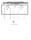
Operation:
Place switch in On position for
spoolgun operation. Place switch in
Off position for wire feeder/MIG
(GMAW) gun operation.
When spoolgun switch is in On
position, spoolgun wire feed speed
is controlled by welding power
source Wire Speed control.