


SECTION
6
SEQUENCE
OF
OPERATION
f%~
WARNING:
ELECTRIC
SHOCK
can
kill;
a~
MOVING
PARTS
can
cause
serious
injury;
IMPROPER
AIRFLOW
AND
EXPOSURE
TO
ENVIRONMENT
can
damage
internal
parts.
Do
not
touch
live
electrical
parts.
Keep
away
from
moving
parts.
Keep
all
covers
and
panels
in
place
while
operating.
Warranty
is
void
if
the
welding
power
source
is
operated
with
any
portion
of
the
outer
enclosure
removed.
ARC
RAYS,
SPARKS,
AND
HOT
SURFACES
can
burn
eyes
and
skin;
NOISE
can
damage
hearing.
Wear
correct
eye,
ear,
and
body
protection.
FUMES
AND
GASES
can
seriously
harm
your
health.
Keep
your
head
out
of
the
fumes.
Ventilate
to
keep
from
breathing
fumes
and
gases.
If
ventilation
is
inadequate,
use
approved
breathing
device.
WELDING
WIRE
can
cause
puncture
wounds.
Do
not
point
gun
toward
any
part
of
the
body,
any
conductive
surface,
or
other
personnel.
HOT
METAL,
SPATTER,
AND
SLAG
can
cause
fire
and
burns.
Watch
for
fire.
Keep
a
fire
extinguisher
nearby,
and
know
how
to
use
it.
Do
not
use
near
flammable
material.
Allow
work
and
equipment
to
cool
before
handling.
MAGNETIC
FIELDS
FROM
HIGH
CURRENTS
can
affect
pacemaker
operation.
Wearers
should
consult
their
doctor before
going
near
arc
welding,
gouging,
or
spot
weld
ing
operations.
See
Section
1
-
Safety
Rules
For
Operation
Of
Arc
Welding
Power
Source
for
basic
welding
safety
information.
6-1.
GAS
METAL
ARC
WELDING
(GMAW)-CON
TINUOUS
AND
GAS
METAL
ARC
WELDING-
PULSED
ARC
(GMAW-P)
IMPORTANT:
Be
sure
that
work
cable
is
installed
into
NEGATIVE
()
weld
output
receptacle
and
weld
cable
from
unit
is
installed
into
POSITIVE
(+)
weld
output
re
ceptacle (see
Section
4-7).
2.
Wear
dry
insulating
gloves
and
clothing.
3.
Thoroughly
clean
joint
area
of
workpiece.
a
CAUTION:
WELDING
CURRENT
can
dam
age
vehicle
computers
and
other
electronic
components.
Disconnect
both
battery
cables
before
weld
ing
on
a
vehicle.
Disconnect
vehicle
computer(s)
before
weld
ing
on
a
vehicle.
Place
work
clamp
as
close
to
the
weld
as
pos
sible
to
avoid
long
electrical
paths.
Be
sure
all
weld
circuit
connections
are
clean
and
tight.
4.
Connect
work
clamp
to
clean,
bare
metal
at
work-
piece.
5.
Select
and
obtain
proper
welding
wire,
and
thread
as
instructed
in
Section
4-13
of
this
Manual.
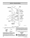
6.
If
applicable,
place
the
Selector
switch
on
the
op
tional
SPW-1
Panel
in
the
CONTINUOUS
posi
tion
if
continuous
welding,
and
place
the
switch
in
the
PULSE
position
if
pulse
welding
(see
Section
5-5).
7.
If
pulse
welding,
rotate
the
SPOT
TIME/PULSE
ON
TIME
and
PULSE
OFF
TIME
control
to
de
sired
settings
(see
Section
5-5).
8.
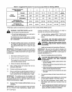
Set
a
voltage
condition
with
the
THICKNESS
VOLTS
selector
plug
that
is
appropriate
for
the
base
metal
thickness
and
type
of
shielding
gas
(see
Section
5-2
and
Table
6-1).
IMPORTANT:
It
is
important
that
the
selected
voltage
be
appropriate
for
type
of
weld
and
thickness
of
material.
Be
sure
that
the
weld
bead
is
thoroughly
fused
with
the
base
metal
along
the
total
length
of
the
bead.
If
the
weld
bead
does
not
penetrate
the
base
metal,
increase
the
weld
voltage.
If
the
edges
of
the
bead
cut
into
the
base
metal,
decrease
weld
voltage.
9.
Rotate
the
FINE
TUNING
WIRE
SPEED
control
to
50.
The
control
can
be
adjusted
as
required
while
welding.
10.
Turn
on
shielding
gas
at
the
source.
11.
Adjust
shielding
gas
pressure,
and
purge
shield
ing
gas
hose
as
follows:
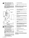
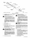
a.
Open
left
side
access
door,
release
pressure
spring
on
drive
roll
assembly,
and
pivot
upper
drive
roll
up
and
away
from
lower
drive
roll.
a
WARNING:
Read
and
follow
safety
informa
tion
at
beginning
of
entire
Section
6
before
proceeding.
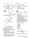
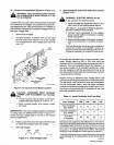
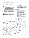
1.
Install
and
connect
unit
according
to
section
4.
OM-113
336
Page
21