


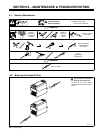
OM-217 769 Page 18
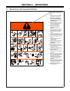
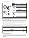
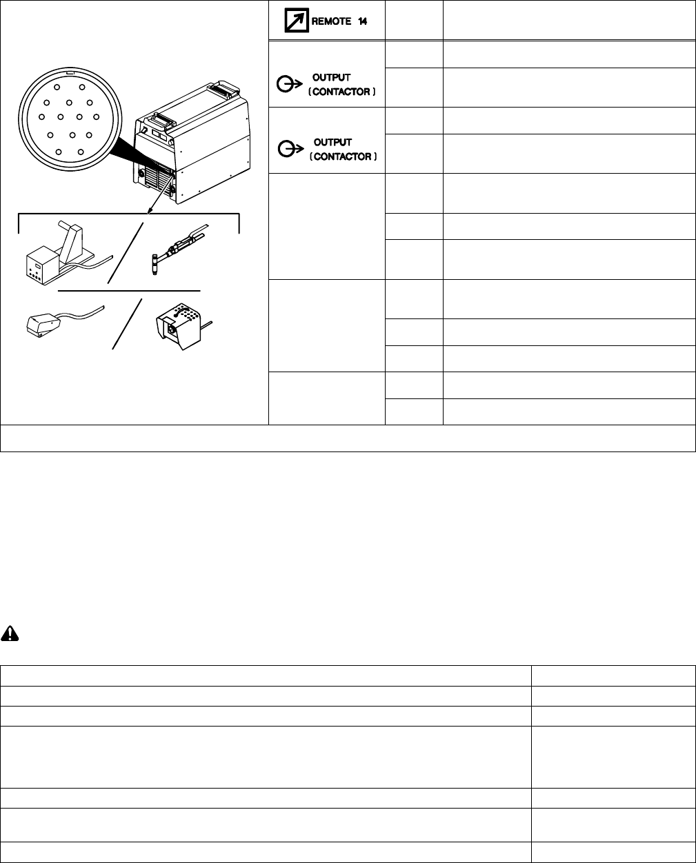
4-7. Remote 14 Receptacle Information
Socket* Socket Information
24 VOLTS AC
A 24 volts ac. Protected by circuit breaker CB2.
AJ
B
K
I
24 VOLTS AC
B Contact closure to A completes 24 volts ac con-
tactor control circuit.
B
I
C
L
NH
115 VOLTS AC
I 115 volts ac. Protected by circuit breaker CB1.
C
D
M
G
E
F
115 VOLTS AC
J Contact closure to I completes 115 volts ac con-
tactor control circuit.
REMOTE
C Output to remote control; 0 to +10 volts dc, +10
volts dc in MIG mode.
REMOTE
OUTPUT
CONTROL
D Remote control circuit common.
CONTROL
E 0 to +10 volts dc input command signal from re-
mote control.
A/V
H Voltage feedback; +1 volt dc per 10 output recep-
tacle volts.
A/V
AMPERAGE
V
O
LTA
G
E
F Current feedback; +1 volt dc per 100 amperes.
ST-801 192
VOLTAGE
M CC/CV select
GND
G Circuit common for 24 and 115 volts ac circuits.
GND
K Chassis common.
*The remaining sockets are not used.
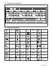
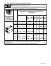
4-8. Electrical Service Guide
NOTICE − INCORRECT INPUT POWER can damage this welding power source. This welding power source requires a CONTINUOUS supply of
input power at rated frequency(+10%) and voltage (+10%). Phase to ground voltage shall not exceed +10% of rated input voltage. Do not use a genera-
tor with automatic idle device (that idles engine when no load is sensed) to supply input power to this welding power source.
NOTICE − Actual input voltage should not be 10% less than minimum and/or 10% more than maximum input voltages listed in table. If actual input
voltage is outside this range, output may not be be available.
Failure to follow these electrical service guide recommendations could create an electric shock or fire hazard. These recommenda-
tions are for a dedicated branch circuit sized for the rated output and duty cycle of the welding power source.
50/60 Hz Three Phase
Input Voltage 400
Input Amperes At Rated Output 18
Max Recommended Standard Fuse Rating In Amperes
1
Time-Delay
2
20
Normal Operating
3
25
Min Input Conductor Size In AWG
4
14
Max Recommended Input Conductor Length In Feet (Meters)
133
(41)
Min Grounding Conductor Size In AWG
4
14
Reference: 2005 National Electrical Code (NEC) (includes article 630)
1 Consult factory for circuit breaker applications.
2 “Time-Delay” fuses are UL class “RK5” .
3 “Normal Operating” (general purpose - no intentional delay) fuses are UL class “K5” (up to and including 60 amp), and UL class “H” ( 65 amp and
above).
4 Conductor data in this section specifies conductor size (excluding flexible cord or cable) between the panelboard and the equipment per NEC Table
310.16. If a flexible cord or cable is used, minimum conductor size may increase. See NEC Table 400.5(A) for flexible cord and cable requirements.