


4
5
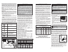
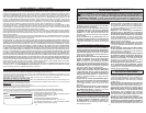
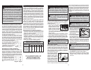
Grounded Tools: Tools with Three Prong Plugs
Tools marked “Grounding Required” have a three
wire cord and three prong grounding plug. The
plug must be connected to a properly grounded
outlet (See Figure A). If the tool should electrically
malfunction or break down, grounding provides a
low resistance path to carry electricity away from
the user, reducing the risk of electric shock.
The grounding prong in the plug is connected
through the green wire inside the cord to the
grounding system in the tool. The green wire in the
cord must be the only wire connected to the tool's
grounding system and must never be attached to
an electrically “live” terminal.
Your tool must be plugged into an ap-
propriate outlet, properly installed and
grounded in accordance with
all codes and ordinances. The
plug and outlet should look like
those in Figure A.
Double Insulated Tools: Tools
with Two Prong Plugs
Tools marked “Double Insulated” do not require
grounding. They have a special double insulation
system which satisfi es OSHA requirements and
complies with the applicable
standards of Underwriters
Laboratories, Inc., the Ca-
nadian Standard Associa-
tion and the National Electri-
cal Code. Double Insulated
tools may be used in either of
the 120 volt outlets shown in
Figures B and C.
Fig. B
Fig. C
Fig. A
GROUNDING
WARNING Improperly connecting the
grounding wire can result in the risk of elec-
tric shock. Check with a qualifi ed electrician
if you are in doubt as to whether the outlet is
properly grounded. Do not modify the plug
provided with the tool. Never remove the
grounding prong from the plug. Do not use
the tool if the cord or plug is damaged. If
damaged, have it repaired by a MILWAUKEE
service facility before use. If the plug will not
fi t the outlet, have a proper outlet installed by
a qualifi ed electrician.
Cat. No. Volts AC Amps No Load RPM
0240-20 120 8 0-2800
Wood Steel Masonry
Cat. No.
Flat
Boring
Bits
Hole
Saws
Twist
Drill
Hole
Saws
Carbide-
Tipped
Bits
0240-20 1” 1-3/4” 3/8” 1” 3/8”
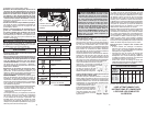
Grounded tools require a three wire extension
cord. Double insulated tools can use either a two
or three wire extension cord. As the distance from
the supply outlet increases, you must use a heavier
gauge extension cord. Using extension cords with
inadequately sized wire causes a serious drop in
voltage, resulting in loss of power and possible tool
damage. Refer to the table shown to determine the
required minimum wire size.
The smaller the gauge number of the wire, the
greater the capacity of the cord. For example, a 14
gauge cord can carry a higher current than a 16
gauge cord. When using more than one extension
cord to make up the total length, be sure each cord
contains at least the minimum wire size required.
If you are using one extension cord for more than
one tool, add the nameplate amperes and use the
sum to determine the required minimum wire size.
Guidelines for Using Extension Cords
• If you are using an extension cord outdoors,
be sure it is marked with the suffi x “W-A” (“W”
in Canada) to indicate that it is acceptable for
outdoor use.
• Be sure your extension cord is properly wired
and in good electrical condition. Always replace
a damaged extension cord or have it repaired by
a qualifi ed person before using it.
• Protect your extension cords from sharp objects,
excessive heat and damp or wet areas.
READ AND SAVE ALL
INSTRUCTIONS FOR FUTURE USE.
* Based on limiting the line voltage drop to
fi ve volts at 150% of the rated amperes.
EXTENSION CORDS
ASSEMBLY
WARNING To reduce the risk of injury,
always unplug tool before attaching or remov-
ing accessories or making adjustments. Use
only specifi cally recommended accessories.
Others may be hazardous.
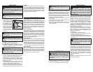
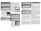
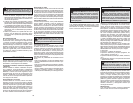
2
1
3
1. Keyless Chuck
2. Forward/Reverse switch
3. Trigger
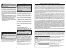
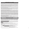
Installing Bits into Keyless Chucks
These tools are equipped with a hand-tightening
keyless chuck. Always unplug the tool before install-
ing or removing bits.
1. To open the chuck jaws,
turn the sleeve counter-
clockwise.
When using drill bits, allow
the bit to strike the bottom
of the chuck. Center the
bit in the chuck jaws and
lift it about 1/16" off of the
bottom.
When using screwdriver bits, insert the bit far
enough for the chuck jaws to grip the hex of the
bit.
2. To close the chuck jaws, hold the collar while
turning the sleeve clockwise. Tighten securely.
WARNING To reduce the risk of injury,
do not grasp the bit while the chuck is rotat-
ing or while the bit is falling from the chuck.
Collar
Sleeve
SYMBOLOGY
SPECIFICATIONS
CAPACITIES
FUNCTIONAL DESCRIPTION
Double Insulated
Amps
Volts
Alternating Current Only
No Load Revolutions
per Minute (RPM)
C
US
Underwriters Laboratories, Inc.
United States and Canada
• Hold power tool by insulated gripping surfaces,
when performing an operation where the cutting
accessory may contact hidden wiring or its
own cord. Cutting accessory contacting a “live”
wire may make exposed metal parts of the power
tool “live” and could give the operator an electric
shock.
• Maintain labels and nameplates. These carry
important information. If unreadable or missing,
contact a MILWAUKEE service facility for a free
replacement.
• WARNING Some dust created by power sanding,
sawing, grinding, drilling, and other construction
activities contains chemicals known to cause
cancer, birth defects or other reproductive harm.
Some examples of these chemicals are:
• lead from lead-based paint
• crystalline silica from bricks and cement and
other masonry products, and
• arsenic and chromium from chemically-treated
lumber.
Your risk from these exposures varies, depending
on how often you do this type of work. To reduce
your exposure to these chemicals: work in a well
ventilated area, and work with approved safety
equipment, such as those dust masks that are spe-
cially designed to fi lter out microscopic particles.
WARNING To reduce the risk of injury,
wear safety goggles or glasses with side
shields.
Chuck Removal
This tool is equipped with a threaded spindle to
hold the chuck. Before removing the chuck, unplug
the tool and open the chuck jaws. A left-handed
thread screw is located inside the chuck to prevent
the chuck from loosening when the tool is oper-
ated in reverse direction. Remove the screw by
turning it clockwise. To
remove the chuck, hold
the tool so that only the
side of the chuck rests
fi rmly and squarely on a
solid workbench. Insert
the chuck key or a chuck
remover bar in one of the
keyholes. Turn the chuck
so the key is at about a
30° angle to the bench
top and strike the key
sharply with a hammer so the chuck turns in a
counterclockwise direction (looking from the front
of the tool). This should loosen the chuck from the
spindle which has a right hand thread making it
easy to remove the chuck by hand.
NOTE: When replacing the chuck, always replace
the left hand thread screw in the chuck.
Recommended Minimum Wire Gauge
For Extension Cords*
Extension Cord Length
Nameplate
Amperes
25' 50' 75' 100' 150'
0 - 2.0
2.1 - 3.4
3.5 - 5.0
5.1 - 7.0
7.1 - 12.0
12.1 - 16.0
16.1 - 20.0
18
18
18
18
16
14
12
18
18
18
16
14
12
10
18
18
16
14
12
10
18
16
14
12
10
16
14
12
12