


4 5
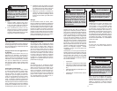
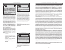
erly grounded outlet (See Figure A). If the tool
should electrically malfunction or break down,
grounding provides a low resistance path to
carry electricity away from the user, reducing
the risk of electric shock.
The grounding prong in the plug is connected
through the green wire inside the cord to the
grounding system in the tool. The green wire
in the cord must be the only wire connected to
the tool's grounding system and must never be
attached to an electrically “live” terminal.
Your tool must be plugged into an appropri-
ate outlet, properly installed and grounded in
accordance with all codes and ordinances.
The plug and outlet should look like those in
Figure A.
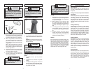
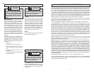
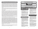
Double Insulated Tools:
Tools with Two Prong Plugs
Grounded Tools:
Tools with Three Prong Plugs
Fig. B Fig. C
Fig. A
Improperly connecting the grounding
wire can result in the risk of electric
shock. Check with a qualifi ed electri-
cian if you are in doubt as to whether
the outlet is properly grounded. Do not
modify the plug provided with the tool.
Never remove the grounding prong
from the plug. Do not use the tool if the
cord or plug is damaged. If damaged,
have it repaired by a MILWAUKEE ser-
vice facility before use. If the plug will
not fi t the outlet, have a proper outlet
installed by a qualifi ed electrician.
GROUNDING
WARNING
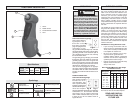
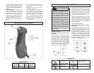
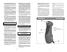
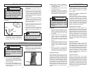
FUNCTIONAL DESCRIPTION
1. Chuck
2. Paddle switch
3. Forward/Reverse switch
4. Cord
2
1
3
4
No Load
RPM
0 - 1300
Volts
AC
120
Catalog
Number
0370-20
Specifi cations
Amps
3.5
Twist Drill
Capacity
in Steel
3/8"
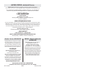
Amperes
Double Insulated
Underwriters
Laboratories, Inc.
Volts Alternating Current
No Load Revolutions
per Minute (RPM)
Symbology
Mexican Approvals
Marking
Tools marked “Ground-
ing Required” have a
three wire cord and
three prong grounding
plug. The plug must be
connected to a prop-
Tools marked “Double
Insulated” do not re-
quire grounding. They
have a special double
insulation system which
satisfi es OSHA require-
ments and complies
with the applicable standards of Underwriters
Laboratories, Inc., the Canadian Standard
Association and the National Electrical
Code. Double Insulated tools may be used
in either of the 120 volt outlets shown in
Figures B and C.
Grounded tools require a three wire exten-
sion cord. Double insulated tools can use
either a two or three wire extension cord.
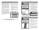
As the distance from the supply outlet
increases, you must use a heavier gauge
extension cord. Using extension cords with
inadequately sized wire causes a serious
drop in voltage, resulting in loss of power
and possible tool damage. Refer to the table
shown to determine the required minimum
wire size.
The smaller the gauge number of the wire,
the greater the capacity of the cord. For ex-
ample, a 14 gauge cord can carry a higher
current than a 16 gauge cord. When using
more than one extension cord to make up
the total length, be sure each cord contains
at least the minimum wire size required. If
you are using one extension cord for more
than one tool, add the nameplate amperes
and use the sum to determine the required
minimum wire size.
Guidelines for Using Extension Cords
• If you are using an extension cord out-
doors, be sure it is marked with the suffi x
“W-A” (“W” in Canada) to indicate that it
is acceptable for outdoor use.
• Be sure your extension cord is prop-
erly wired and in good electrical
condition. Always replace a damaged
extension cord or have it repaired by a
qualifi ed person before using it.
• Protect your extension cords from sharp
objects, excessive heat and
damp or wet areas.
EXTENSION CORDS
READ AND SAVE ALL
INSTRUCTIONS FOR
FUTURE USE.
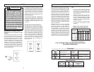
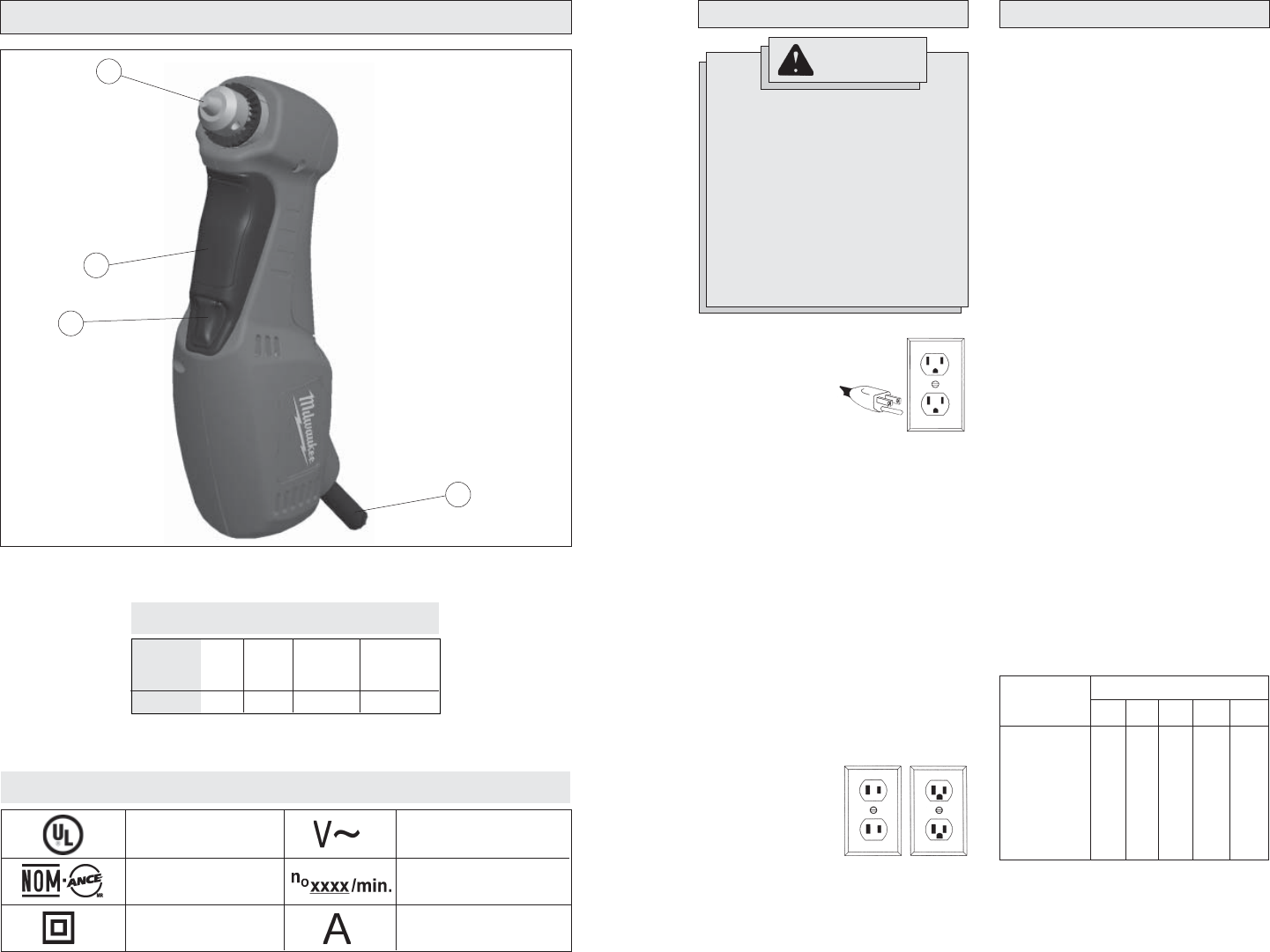
Recommended Minimum Wire Gauge
for Extension Cords*
Extension Cord Length
* Based on limiting the line voltage drop to
fi ve volts at 150% of the rated amperes.
Nameplate
Amperes
0 - 2.0
2.1 - 3.4
3.5 - 5.0
5.1 - 7.0
7.1 - 12.0
12.1 - 16.0
16.1 - 20.0
25'
18
18
18
18
16
14
12
75'
18
18
16
14
12
10
100'
18
16
14
12
10
150'
16
14
12
12
50'
18
18
18
16
14
12
10