


4
5
OPERATION
WARNING To reduce the risk of injury,
wear safety goggles or glasses with side
shields.
WARNING Always remove battery
pack before changing or removing acces-
sories. Only use accessories specifically
recommended for this tool. Others may be
hazardous.
WARNING Recharge only with the
charger specifi ed for the battery. For specifi c
charging instructions, read the operator’s
manual supplied with your charger and
battery.
WARNING Always lock trigger or
remove battery pack before changing or re-
moving accessories. Only use accessories
specifi cally recommended for this tool. Others
may be hazardous.
Specifi cations
Steel
1/2"
Wood
Flat
Bit
1-1/2"
Auger
Bit
1-1/2"
Hole
Saw
2-9/16"
Screws
(dia.)
1/4"
Masonry
1/2"
Cat. No.
0724-20
Volts
DC
28
No Load
RPM
Low 0-600
High 0-1800
No Load
Blows per
Minute
Low 0-9000
High 0-27000
Capacities
Removing Battery Pack from Tool
Push in the release buttons and pull the battery
pack away from the tool.
Inserting Battery Pack into Tool
The battery pack can be inserted into the tool in
two ways. To insert the battery pack onto the tool,
slide the pack onto the body of the tool. Make sure
it latches securely into place.
Installing the Side Handle
1. To install the side handle, loosen the side handle
grip until the ring is large enough to slide over
the torque selector collar. The raised rib on the
side handle ring fi ts inside the groove around the
tool. Rotate the handle to the desired position
and tighten the side handle until it is secure.
2. To remove the side handle, loosen the side
handle grip until the ring is large enough to slide
off the tool.
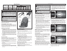
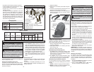
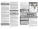
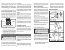
Clip-Lok
TM
System
The Clip-Lok system consists of three pieces; the
belt clip, the tool holder, and the bit holder.
The system is shipped assembled for right-handed
use. To change the assembly for left-handed use:
1. Remove battery pack.
2. Remove screws holding the tool holder and the
bit holder.
3. Lift the holders at the narrow end and pull the
front tangs out of their slots.
4. Replace the pieces onto the desired side by slid-
ing the tangs into the slots. Tighten the screws
securely.
Bit
holder
Fig. 1
Belt clip
Tool release lever
Stud
Pin
Clamp
Clamp
release
Tool
holder
Front tangs
Attaching the Belt Clip
The belt clip can be mounted to tool belts, bags,
buckets, etc. To mount the belt clip:
1. Pull up the clamp release. The clamp will pop
out.
2. Slide clamp over the tool belt, bag, bucket, etc.
3. Press in the clamp to tighten.
Using the Clip-Lok Tool Holder
1. To attach the tool to the belt clip, slide the tool
holder over the stud on the belt clip until it is held
in place by the protruding pin.
2. To release the tool from the belt clip, grasp the
tool handle, push down on the tool release lever
with your thumb, and pull up on the tool.
Using the Clip-Lok Bit Holder
The bit holder holds two standard 1/4" hex shank
bits up to two inches long.
1. Insert the bit by pressing it into the clip.
2. Remove the bit by lifting the tip of the bit and
pulling it out of the clip.
ASSEMBLY
Using Keyless Chucks
Your cordless tool is equipped with a spindle lock.
The chuck can be tightened with one hand, creating
higher grip strengths on the bit.
Always remove the battery pack or lock the trigger
before inserting or removing bits.
1. To open the chuck jaws, turn the sleeve in the
counterclockwise direction.
When using drill bits, allow the bit to strike the
bottom of the chuck. Center the bit in the chuck
jaws and lift it about 1/16" off of the bottom.
When using screwdriver bits, insert the bit far
enough for the chuck jaws to grip the hex of the
bit.
2. To close the chuck jaws, turn the sleeve in the
clockwise direction. The bit is secure when the
chuck makes a ratcheting sound and the sleeve
can not be rotated any further.
3. To remove the bit, turn the sleeve in the coun-
terclockwise direction.
NOTE: A ratcheting sound may be heard when the
chuck is opened or closed. This noise is part of the
locking feature, and does not indicate a problem
with the chuck's operation.
Selecting Speed
The speed selector is on top of the motor housing.
Allow the tool to come to a complete stop before
changing speeds. See “Applications” for recom-
mended speeds under various conditions.
1. For Low speed (up to 600 RPM), push the
speed selector to the left.
2. For High speed (up to 1800 RPM), push the
speed selector to the right.
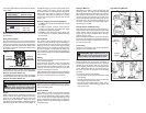
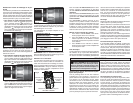
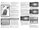
Selecting Hammer or Drill Action
MILWAUKEE Hammer-Drills are designed for three
operating modes: drilling with hammering action,
drilling only, and driving screws. To set the operating
mode, rotate the hammer/drill selector collar and
torque selector collar to the desired symbols.
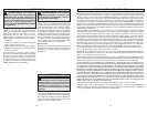
Fig. 2
To Hammer
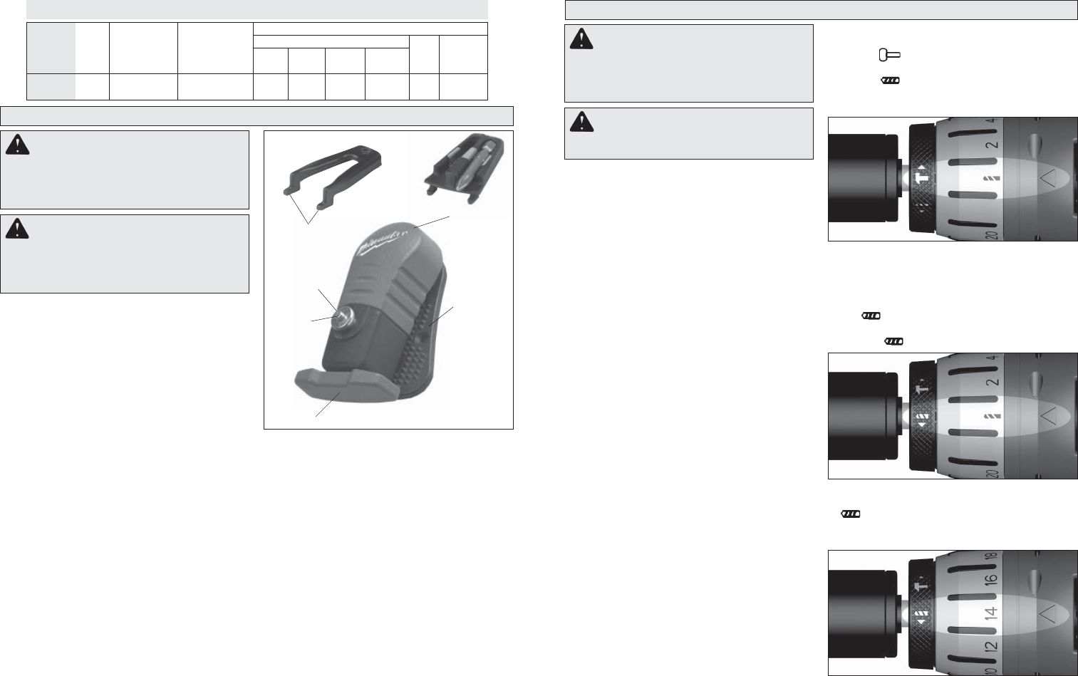
Fig. 3
To Drill
Fig. 4
To Drive Screws
1. To use the hammer-drilling mode, rotate the
hammer/drill selector collar until the hammer
symbol
appears in line with the arrow. Then
rotate the Torque selector collar until the drill
symbol appears in line with the arrow. Ap-
ply pressure to the bit to engage the hammering
mechanism.
NOTE: When using carbide bits, do not use water to
settle dust. Do not attempt to drill through steel rein-
forcing rods. This will damage the carbide bits.
2. To use the drilling only mode, rotate the
hammer/drill selector collar until the drill sym-
bol
appears in line with the arrow. Then
rotate the Torque selector collar until the drill
symbol appears in line with the arrow.
3. To use the driving screws mode, rotate the
hammer/drill selector collar until the drill symbol
appears in line with the arrow. Then rotate
the torque selector collar until the desired clutch
setting appears in line with the arrow.
The adjustable clutch ,when properly adjusted, will
slip at a preset torque to prevent driving the screw
too deep into different materials and to prevent
damage to the screw or tool.