


10 11
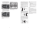
Fig. 7
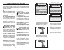
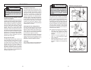
To Drill
Fig. 8
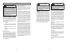
To Drive Screws
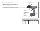
2. To use the drilling only mode (Fig. 7),
rotate the hammer/drill selector collar
until the drill symbol appears in line
with the arrow. Then rotate the Torque
selector collar until the drill symbol
mmm
appears in line with the arrow.
The adjustable clutch ,when properly ad-
justed, will slip at a preset torque to prevent
driving the screw too deep into different
materials and to prevent damage to the
screw or tool.
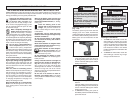
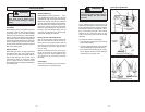
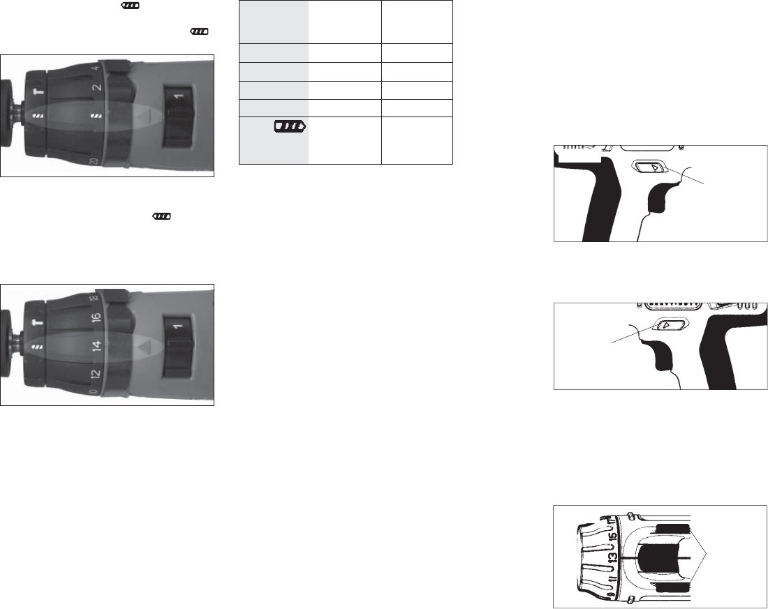
For reverse (counterclockwise) rotation,
push in the control switch from the left side
of the tool (Fig. 10). Check direction of
rotation before use.
Using Control Switch (Fig. 9, 10, and 11)
The control switch may be set to three posi-
tions: forward, reverse and lock. Due to a
lockout mechanism, the control switch can
only be adjusted when the ON/OFF switch
is not depressed. Always allow the motor to
come to a complete stop before using the
control switch.
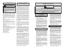
For forward (clockwise) rotation, push in the
control switch from the right side of the tool
(Fig. 9). Check the direction of rotation
before use.
Push in
for forward
Fig. 9
Fig. 10
Push in
for reverse
To lock the trigger, push the control switch
to the center position (Fig. 11). The trigger
will not work while the control switch is in
the center locked position. Always lock the
trigger or remove the battery pack before
performing maintenance, changing acces-
sories, storing the tool and any time the tool
is not in use.
3. To use the driving screws mode
(Fig. 8), rotate the hammer/drill selector
collar until the drill symbol appears
in line with the arrow. Then rotate the
torque selector collar until the desired
clutch setting appears in line with the
arrow.
Fig. 11
Push to
center
position to
lock trigger
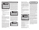
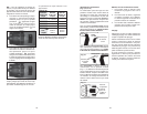
The torque specifications shown here are ap-
proximate values.
NOTE: Because the above settings are only
a guide, use a piece of scrap material to test
the different clutch positions before driving
screws into the workpiece.
Torque
selector
collar setting
1 - 5
6 - 10
11 - 15
16 - 20
Drill
Low
High
0 - 17 in. lbs.
21 - 38 in. lbs.
42 - 60 in. lbs.
65 - 85 in. lbs.
460 in. lbs.
160 in. lbs.
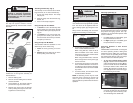
0615-20
& 0617-20
Torque
0 - 17 in. lbs.
21 - 38 in. lbs.
42 - 60 in. lbs.
65 - 85 in. lbs.
495 in. lbs.
175 in. lbs.
0625-20
& 0627-20
Torque
Starting, Stopping and Controlling
Speed
1. To start the tool, grasp the handle fi rmly
and pull the trigger.
2. To vary the speed, increase or decrease
the pressure on the trigger. The further
the trigger is pulled, the greater the
speed.
3. To stop the tool, release the trigger.
Make sure the bit comes to a complete
stop before laying the tool down.
Drilling
Set both the hammer/drill and torque selector
collars to the drill positions.
Place the bit on the work surface and ap-
ply fi rm pressure before starting. Too much
pressure will slow the bit and reduce drilling
effi ciency. Too little pressure will cause the
bit to slide over the work area and dull the
point of the bit.
If the tool begins to stall, reduce pressure
slightly to allow the bit to regain speed. If
the bit binds, reverse the motor to free the
bit from the workpiece.