


4
5
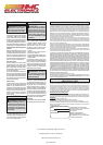
Direct Current
Volts
No Load Revolutions per Minute
(RPM)
Underwriters Laboratories, Inc.
United States and Canada
• Hold power tool by insulated gripping sur-
faces, when performing an operation where the
fastener may contact hidden wiring. Fasteners
contacting a “live” wire may make exposed metal
parts of the power tool “live” and could give the
operator an electric shock.
• Keep hands away from all cutting edges and
moving parts.
• Maintain labels and nameplates. These carry
important information. If unreadable or missing,
contact a MILWAUKEE service facility for a free
replacement.
• WARNING: Some dust created by power sanding,
sawing, grinding, drilling, and other construction
activities contains chemicals known to cause
cancer, birth defects or other reproductive harm.
Some examples of these chemicals are:
• lead from lead-based paint
• crystalline silica from bricks and cement and other
masonry products, and
• arsenic and chromium from chemically-treated
lumber.
Your risk from these exposures varies, depending
on how often you do this type of work. To reduce
your exposure to these chemicals: work in a well
ventilated area, and work with approved safety
equipment, such as those dust masks that are spe-
cially designed to fi lter out microscopic particles.
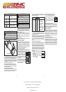
3
1
2
4
6
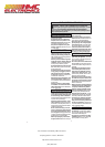
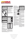
1. Bit holder collar
2. Clutch adjusting ring
3. Speed selector
4. Lock switch
5. Fuel Gauge
6. Forward/reverse switch
5
FUNCTIONAL DESCRIPTION
SYMBOLOGY
SPECIFICATIONS
Cat. No. Volts DC No Load RPM
2101-20 4 Low 200
High 600
SPECIFIC SAFETY RULES
• When battery pack is not in use, keep it away
from other metal objects like paper clips,
coins, keys, nails, screws, or other small metal
objects that can make a connection from one
terminal to another. Shorting the battery termi-
nals together may cause burns or a fi re.
• Under abusive conditions, liquid may be eject-
ed from the battery; avoid contact. If contact
accidentally occurs, f ush with water. If liquid
contacts eyes, additionally seek medical help.
Liquid ejected from the battery may cause irritation
or burns.
SERVICE
• Have your power tool serviced by a quali f ed
repair person using only identical replacement
parts. This will ensure that the safety of the power
tool is maintained.
WARNING Recharge only with
the charger specified for the battery . For
specific charging instructions, read the
operator’s manual supplied with your charger
and battery.
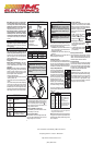
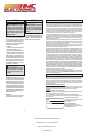
Inserting the Battery into the Tool
1
Slot
Tab
Line
Lock
Line up the tabs on the battery with the slots in the
tool opening. Slide the battery all the way into the
tool. Turn the battery clockwise to lock it in place.
The line on the battery will line up with the
on
the tool. The tool will not run if the battery is not
properly locked into the tool.
Removing the Battery from the Tool
Turn the battery cap counterclockwise to unlock.
Pull the battery out of the tool.
Checking the Fuel Gauge
To determine the amount of charge left in the bat-
tery, press the forward/reverse switch. The Fuel
Gauge will light up for 2-3 seconds.
ASSEMBLY
2
WARNING To reduce the risk of injury,
wear safety goggles or glasses with side-
shields.
WARNING Always remove battery
pack before changing or removing ac-
cessories. Only use accessories specif cally
recommended for this tool. Others may be
hazardous.
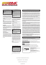
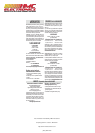
Installing Bits
Always remove the battery before inserting or
removing bits. Select the proper style and size bit
for the type of screw you are using.
1. To install the bit, pull out the collar. Press the bit
into the socket until the collar snaps back and
the bit is locked into place.
2. To remove the bit, pull out the collar, then pull
out the bit.
NOTE: It is not necessary to hold the collar out
when installing and removing bits.
Adjusting the Handle
The handle is designed for convenience and con-
trol. The durable, center pivot allows the handle to
be used in the conventional shape or folded into a
pistol grip. Access to the forward/reverse switch and
lock switch is comfortable in either handle position.
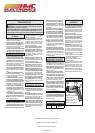
Using the Adjustable Clutch
This tool has an adjustable clutch
for driving different types of screws
into different materials. When prop-
erly adjusted, the clutch will slip at
a preset torque to prevent driving
the screw too deep and to prevent
damage to the screw or tool.
To adjust the clutch, turn the clutch
adjusting ring so that the desired
setting (1-21) lines up with the arrow
on the motor housing, as shown.
The torque specifications shown here are ap-
proximate values obtained with a fully charged
battery pack.
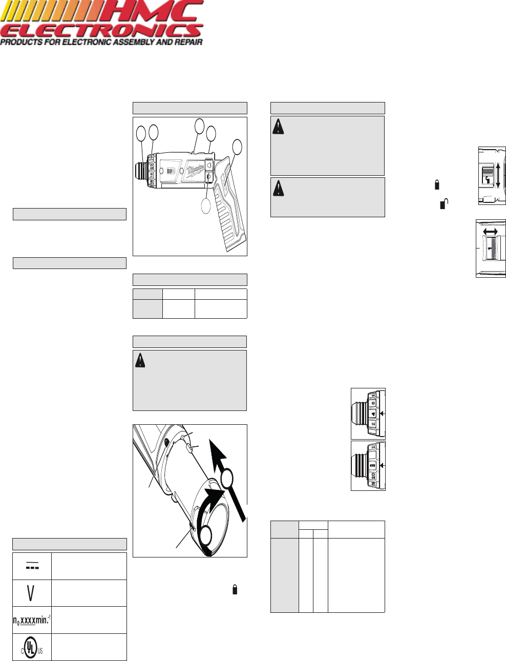
Using the Lock Switch
When the battery is installed, the tool is in operat-
ing condition. The lock switch prevents accidental
starting by locking the forward/reverse switch. Al-
ways set the lock switch to “lock” before performing
maintenance, changing accessories,
storing the tool and any time the tool
is not in use.
1. To lock, push the lock switch to
display the lock
symbol.
2. To unlock, push the lock switch to
display the unlock
symbol.
Selecting High or Low Speed
1. For low speed and more torque,
push the speed selector back ("1"
is displayed).
2. For high speed and less torque,
push the speed selector forward
("2" is displayed).
Selecting Forward or Reverse
Press and hold the top of the switch ◄ for forward
rotation, and the bottom of the switch ► for reverse
rotation. The switch will automatically return to the
center OFF position when it is released.
Automatic Shut-Off
To prevent extra driving force after the selected
torque has been reached, the tool will automatically
shut off if the clutch slips. At higher clutch settings,
this feature may not immediately engage. Release
the switch to reset the automatic shut-off.
Cold Weather Operation
MILWAUKEE Lithium-Ion battery packs are de-
signed to operate in temperatures below freezing.
When the battery pack is too cold, it may need to
warm up before normal use. Put the battery on a
tool and use the tool in a light application. It may
“buzz” for a short time until it warms up. When the
buzzing stops, use the tool normally.
Unlock
Lock
OPERATION
Clutch
Setting
(in lbs)
Applications
Lo Hi
1
4
7
10
13
16
19
3.7
6.5
9.3
12.8
16.4
20.0
23.4
3.7
6.5
9.3
11.2
N/A
N/A
N/A
Small screws in softwood.
Medium screws in soft-
wood or small screws in
hardwood.
Large screws in soft-
woods. Medium screws in
hardwood or large screws
in hardwood with pilot
hole.
Drilling
Driving
HI LO
* When set to high speed, set the clutch at 10 or below.
The Automatic Shut-Off may not work at higher clutch
settings (see "Automatic Shut-Off").
NOTE: Because the settings shown in the table are
only a guide, use a piece of scrap material to test
the different clutch settings before driving screws
into the workpiece.
Documentation Provided By HMC Electronics
33 Springdale Ave. Canton, MA 02021
http://www.hmcelectronics.com
(800) 482-4440