


9
10
11
12
13
3
3
2
2
1
1
4
4
8
8
7
6
5
5
6
7
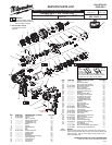
Terminals, Connectors and 1 or 2 End Wire Preparation
Wire
Color
Origin or
Gauge
Wire
No.
Length
WIRING SPECIFICATIONS
1 Black 23-30-0590 ----- Component of the motor assembly.
2 Red 23-30-0590 ----- Component of the motor assembly.
3 White 23-66-2736 ----- Component of the switch assembly.
4 Black 23-66-2736 ----- Component of the switch assembly.
5 Black 23-66-2736 ----- Component of the switch assembly.
6 Red 23-66-2736 ----- Component of the switch assembly.
7 White 23-66-2736 ----- Component of the switch assembly.
8 Red 23-66-2736 ----- Component of the switch assembly.
9 Red 23-66-2736 ----- Component of the switch assembly.
10 Yellow 23-66-2736 ----- Component of the switch assembly.
11 Blue 23-66-2736 ----- Component of the switch assembly.
12 Black 23-66-2736 ----- Component of the switch assembly.
13 Sleeve 23-66-2736 ----- Component of the switch assembly / fuel gauge LED.
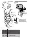
MOTOR
ASSEMBLY
FUEL GUAGE
LED ASSY.
SLEEVED WIRES
(White, black, red,
green and gray)
ROUTE WIRES 1 AND 2
THROUGH TRAPS IN
THIS AREA.
WIRE TIE
FOR 2, 5 & 6
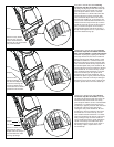
AS AN AID TO REASSEMBLY, TAKE NOTICE OF WIRE ROUTING AND
POSITION IN WIRE GUIDES AND TRAPS WHILE DISMANTLING TOOL
BE CAREFUL AND
AVOID PINCHING
WIRES BETWEEN
HANDLE HALVES
WHEN ASSEMBLING.
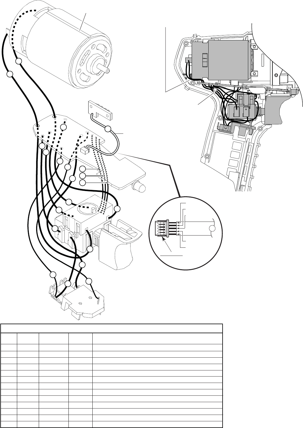
WHITE
BLACK
RED
GREEN
GRAY
13
PINNED SIDE OF CONNECTOR
TO FACE DOWN WHEN
INSTALLING TO
PC BOARD
NOTE:
POSITION CONNECTOR PORTION
OF #13 WITH OPEN PINNED SIDE
FACING DOWN TOWARDS THE
PCB (WHITE WIRE SHOULD FACE
FRONT OF TOOL). BE SURE THAT
THE CONNECTOR IS FULLY SEATED.
PCB
CONNECTOR
BLOCK
ASSEMBLY
SWITCH
ORIENT MOTOR ASSEMBLY
WITH SLOT TO THE TOP