


4
5
SPECIFIC SAFETY RULES
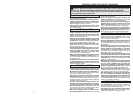
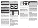
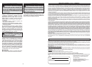
1. Keyless Chuck
2. Worklight/Torque LEDs
3. Paddle Switch
• Wear ear protectors with impact drilling. Expo-
sure to noise can cause hearing loss.
• Use auxiliary handle(s), if supplied with the
tool. Loss of control can cause personal injury.
• Hold power tools by insulated gripping surfaces,
when performing an operation where the cutting
accessory may contact hidden wiring or its own
cord. Cutting accessory contacting a “live” wire
may make exposed metal parts of the power tool
“live” and could give the operator an electric shock.
• Keep hands away from all cutting edges and
moving parts.
• Maintain labels and nameplates. These carry
important information. If unreadable or missing,
contact a MILWAUKEE service facility for a free
replacement.
• WARNING: Some dust created by power sanding,
sawing, grinding, drilling, and other construction
activities contains chemicals known to cause
cancer, birth defects or other reproductive harm.
Some examples of these chemicals are:
• lead from lead-based paint
• crystalline silica from bricks and cement and other
masonry products, and
• arsenic and chromium from chemically-treated
lumber.
Your risk from these exposures varies, depending
on how often you do this type of work. To reduce
your exposure to these chemicals: work in a well
ventilated area, and work with approved safety
equipment, such as those dust masks that are
specially designed to fi lter out microscopic particles.
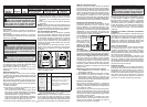
Cat. No.
Volts
DC
No
Load
RPM
Capacities
Drilling
in Wood
(twist bit)
Drilling
in Wood
(spade bit)
Driving
Screws
2415-20 12 0-800 3/8" 1"
1/4”
diameter
• When battery pack is not in use, keep it away
from other metal objects like paper clips,
coins, keys, nails, screws, or other small metal
objects that can make a connection from one
terminal to another. Shorting the battery termi-
nals together may cause burns or a fi re.
• Under abusive conditions, liquid may be eject-
ed from the battery; avoid contact. If contact
accidentally occurs, fl ush with water. If liquid
contacts eyes, additionally seek medical help.
Liquid ejected from the battery may cause irritation
or burns.
SERVICE
• Have your power tool serviced by a qualifi ed
repair person using only identical replacement
parts. This will ensure that the safety of the power
tool is maintained.
FUNCTIONAL DESCRIPTION
ASSEMBLY
WARNING Recharge only with the
charger specifi ed for the battery. For
specifi c charging instructions, read the opera-
tor’s manual supplied with your charger and
battery.
Inserting/Removing the Battery
To remove the battery, push in the release buttons
and pull the battery pack away from the tool.
To insert the battery, slide the pack into the body of
the tool. Make sure it latches securely into place.
OPERATION
WARNING Always remove battery
pack before changing or removing ac-
cessories. Only use accessories specifi cally
recommended for this tool. Others may be
hazardous.
WARNING To reduce the risk of injury,
wear safety goggles or glasses with side
shields.
SYMBOLOGY
Direct Current
Underwriters Laboratories, Inc.
United States and Canada
No Load Revolutions
per Minute (RPM)
SPECIFICATIONS
4. Control Switch
5. Fuel Gauge
6. Clutch Adjusting Dial
1
2
6
5
3
4
Fuel Gauge
To determine the amount of charge left in the bat-
tery, pull the trigger. The Fuel Gauge will light up
for 2-3 seconds.
To signal the end of charge, 1 light on the fuel gauge
will fl ash for 2-3 seconds.
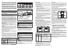
Driving Drilling
Installing Bits
Always remove the battery before inserting or
removing bits. Select the proper style and size bit
for the application.
This tool is equipped with a spindle lock. The chuck
can be tightened with one hand, creating higher grip
strengths on the bit.
Remove the battery pack.1.
To open the chuck jaws, turn the sleeve in the 2.
counterclockwise direction.
When using drill bits, allow the bit to strike the
bottom of the chuck. Center the bit in the chuck
jaws and lift it about 1/16” off of the bottom.
When using screwdriver bits, insert the bit far
enough for the chuck jaws to grip the hex of the
bit.
To close the chuck jaws, turn the sleeve in the 3.
clockwise direction. The bit is secure when the
chuck makes a ratcheting sound and the sleeve
can not be rotated any further.
To remove the bit, turn the sleeve in the counter-4.
clockwise direction.
NOTE: A ratcheting sound may be heard when the
chuck is opened or closed. This noise is part of the
locking feature, and does not indicate a problem
with the chuck’s operation.
Using the Adjustable Clutch
This tool has an adjustable clutch for driving differ-
ent types of screws into different materials. When
properly adjusted, the clutch will slip at a preset
torque to prevent driving the screw too deep and
to prevent damage to the screw or tool.
To adjust the clutch, turn the clutch adjusting dial
so that the desired setting lines up with the arrow
on the motor housing, as shown.
Clutch
Setting
Torque
(in. lbs)
Applications
1-4
5-7
8-11
Drill
13-21
24-35
42-53
125 *
Small screws in softwood.
Medium screws in softwood or
small screws in hardwood.
Large screws in softwoods. Me-
dium screws in hardwood or large
screws in hardwood with pilot hole.
Torque LED
When the maximum torque output for the clutch
setting is reached, the tool will stop and the red
Torque LED will fl ash. Release the switch to reset.
For example, when the clutch adjusting dial is set
to 8, torque over 42 inch pounds will cause the tool
to stop and the red Torque LED to fl ash.
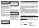
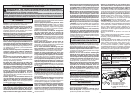
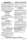
Using Control Switch
The control switch may be set to three positions:
forward, reverse and lock. Due to a lockout mecha-
nism, the control switch can only be adjusted when
the ON/OFF switch is not pressed. Always allow the
motor to come to a complete stop before using the
control switch.
For Forward (clock-
wise) rotation, push
the control switch
as shown. Check
the direction of
rotation before
use.
For Reverse (coun-
terclockwise) rota-
tion, push the control switch as shown. Check
direction of rotation before use.
To Lock the trigger, push the control switch to
the center position. The trigger will not work while
the control switch is in the center locked position.
Always lock the trigger or remove the battery
pack before performing maintenance, changing
accessories, storing the tool and any time the tool
is not in use.
Starting, Stopping and Controlling Speed
1. To start the tool, pull the paddle switch.
2. To stop the tool, release the paddle switch.
3. To vary the driving speed, increase or decrease
pressure on the paddle switch. The further the
paddle switch is pulled, the greater the speed.
Battery Pack Protection
To protect the battery from damage and extend
its life, the tool’s intelligent circuit monitors current
draw, temperature, and voltage drops.
In extremely high torque, binding, stalling, and short
circuit situations that cause high current draw, the
fuel gauge will fl ash and then the tool will turn OFF.
To reset, release the trigger.
Under extreme circumstances, the internal tem-
perature of the battery could become too high.
If this happens, the fuel gauge will fl ash and the
battery pack will shut off. Let the battery pack cool
and then continue work.
FORWARD
REVERSE
LOCK
Push to
CENTER
The torque specifications shown here are ap-
proximate values obtained with a fully charged
battery pack.
* Max developed torque when using MILWAUKEE
XC battery pack. Otherwise, max developed
torque is 100 in. lbs.
NOTE: Because the settings shown in the table are
only a guide, use a piece of scrap material to test
the different clutch settings before driving screws
into the workpiece.