


4
5
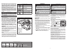
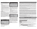
FUNCTIONAL DESCRIPTION
SPECIFICATIONS
Cat. No. Volts DC
No Load
RPM
No Load
Blows per
Minute
Capacities
Drill Only Rotary Hammer (concrete)
Steel Wood Carbide Tipped Percussion Bit
2416-20 12 0 - 900 0 - 6200 3/8" 1/2" 5/8"
SYMBOLOGY
• Wear ear protectors. Exposure to noise can
cause hearing loss.
• Use auxiliary handle(s), if supplied with the
tool. Loss of control can cause personal injury.
• Hold power tools by insulated gripping sur-
faces, when performing an operation where
the cutting tool may contact hidden wiring.
Cutting accessory contacting a “live” wire may
make exposed metal parts of the power tool “live”
and could give the operator an electric shock.
• Maintain labels and nameplates. These carry
important information. If unreadable or missing,
contact a MILWAUKEE service facility for a free
replacement.
• WARNING Some dust created by power sanding,
sawing, grinding, drilling, and other construction
activities contains chemicals known to cause
cancer, birth defects or other reproductive harm.
Some examples of these chemicals are:
• lead from lead-based paint
• crystalline silica from bricks and cement and other
masonry products, and
• arsenic and chromium from chemically-treated
lumber.
Your risk from these exposures varies, depending
on how often you do this type of work. To reduce
your exposure to these chemicals: work in a well
ventilated area, and work with approved safety
equipment, such as those dust masks that are spe-
cially designed to fi lter out microscopic particles.
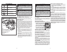
1. LED
2. SDS Plus bit holder
3. Release collar
4. Mode selector
5. Fuel gauge
6. Control switch
7. Trigger
4
7
3
1
2
6
5
Volts
Direct Current
No Load Revolutions per
Minute (RPM)
BPM
Blows per Minute (BPM)
Underwriters Laboratories, Inc.
United States and Canada
SPECIFIC SAFETY RULES
• When battery pack is not in use, keep it away
from other metal objects like paper clips,
coins, keys, nails, screws, or other small metal
objects that can make a connection from one
terminal to another. Shorting the battery termi-
nals together may cause burns or a fi re.
• Under abusive conditions, liquid may be eject-
ed from the battery; avoid contact. If contact
accidentally occurs, fl ush with water. If liquid
contacts eyes, additionally seek medical help.
Liquid ejected from the battery may cause irritation
or burns.
SERVICE
• Have your power tool serviced by a qualifi ed
repair person using only identical replacement
parts. This will ensure that the safety of the power
tool is maintained.
OPERATION
WARNING To reduce the risk of injury,
keep hands away from the bit and all moving
parts. Always wear safety goggles or glasses
with side shields.
Fuel Gauge
To determine the amount of charge left in the bat-
tery, pull the trigger. The Fuel Gauge will light up
for 2-3 seconds.
To signal the end of charge, 1 light on the fuel
gauge will fl ash for 2-3 seconds.
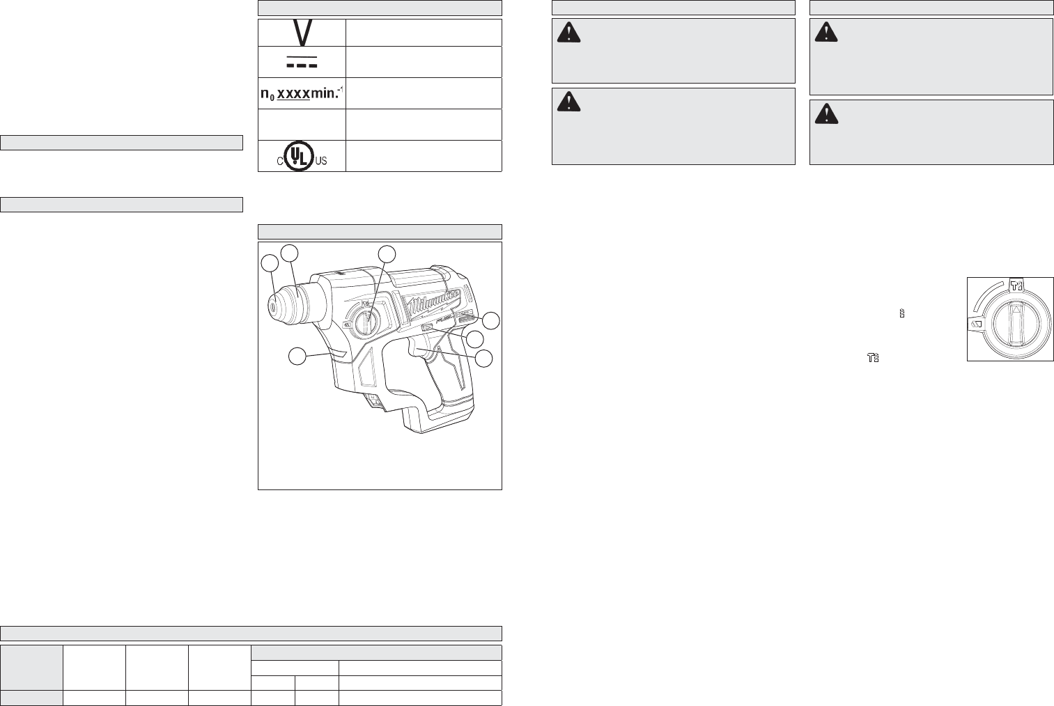
Selecting Action
Always allow the motor to come to a complete stop
before changing the mode selection to avoid dam-
age to the tool.
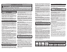
1. For drilling, turn the mode
selector so the arrow points
to the twist drill symbol.
2. For rotary hammering, turn
the mode selector so the ar-
row points to the hammer and
twist drill symbol.
NOTE: To engage the hammering mechanism,
maintain pressure on the bit. When pressure on
the bit is released, the hammering action will stop.
Using the Control Switch
The control switch may be set to three positions:
forward, reverse and lock. Always allow the motor
to come to a complete stop before using the control
switch to avoid damage to the tool.
For forward (clockwise) rotation, push in the control
switch from the right side of the tool. Check the
direction of rotation before use.
For reverse (counterclockwise) rotation, push in the
control switch from the left side of the tool. Check
direction of rotation before use.
To lock the trigger, push the control switch to the
center position. The trigger will not work while the
control switch is in the center locked position. Always
lock the trigger or remove the battery pack before
performing maintenance, changing accessories,
storing the tool and any time the tool is not in use.
WARNING Always remove battery
pack before changing or removing acces-
sories. Only use accessories specifically
recommended for this tool. Others may be
hazardous.
ASSEMBLY
WARNING Recharge only with the
charger specifi ed for the battery. For specifi c
charging instructions, read the operator’s
manual supplied with your charger and battery.
Inserting/Removing the Battery
To remove the battery, push in the release buttons
and pull the battery pack away from the tool.
To insert the battery, slide the pack into the body
of the tool. Make sure it latches securely into place.
Installing Bits
NOTE: Only use accessories with SDS or SDS
Plus shanks.
Be sure that the shank of the bit is clean. Dirt par-
ticles may cause the bit to line up improperly. Do not
use bits larger than the maximum recommended
capacity of the drill because gear damage or mo-
tor overloading may result. For best performance,
be sure that the bit is properly sharpened and the
shank is lightly greased before use.
1. Insert the bit into the nose of the tool.
2. Rotate bit slowly until it aligns with the locking
mechanism.
3. Push bit into tool until it locks.
4. Check that the bit is locked properly; it should
be possible to pull the bit back and forth slightly
(about 1/4”).
5. To remove bits, pull bit holder release collar
toward the rear of tool and remove bit.
NOTE: Use caution when handling hot bits.
WARNING Always remove battery
pack before changing or removing acces-
sories. Only use accessories specifically
recommended for this tool. Others may be
hazardous.