


4
5
OPERATION
WARNING To reduce the risk of injury,
wear safety goggles or glasses with side
shields.
WARNING Always remove battery
pack before changing or removing acces-
sories. Only use accessories specifically
recommended for this tool. Others may be
hazardous.
Cat. No.
Volts
DC
No Load
RPM
Capacities
Steel Flat Bit Auger Bit Hole Saw Screws (dia.)
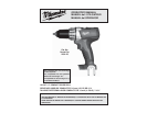
2601-20 18 *
Low 0 - 350
High 0 - 1 400
1/2”
1/2”
1-1/8”
1-1/8”
1”
N/A
2-1/8”
2-1/8”
1/4”
1/4”
Specifi cations
* Cat. No. 2601-20 is not compatible with V™-technology or NiCd systems.
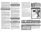
ASSEMBLY
Inserting/Removing Battery Pack
Insert the battery pack from the front by sliding
battery pack into the body of the tool. Insert the
battery pack until the battery latches lock.
To remove the battery pack, press in both battery
latches and slide the battery pack off of the tool.
Using Keyless Chucks
This tool is equipped with a spindle lock. The chuck
can be tightened with one hand, creating higher grip
strengths on the bit.
Always remove the battery pack or lock the trigger
before inserting or removing bits.
WARNING Recharge only with the
charger specifi ed for the battery. For specifi c
charging instructions, read the operator’s
manual supplied with your charger and
battery. This tool is not compatible with V™-
technology or NiCd systems.
1. To open the chuck jaws, turn the sleeve in the
counterclockwise direction.
When using drill bits, allow the bit to strike the
bottom of the chuck. Center the bit in the chuck
jaws and lift it about 1/16" off of the bottom.
When using screwdriver bits, insert the bit far
enough for the chuck jaws to grip the hex of the
bit.
2. To close the chuck jaws, turn the sleeve in the
clockwise direction. The bit is secure when the
chuck makes a ratcheting sound and the sleeve
can not be rotated any further.
3. To remove the bit, turn the sleeve in the coun-
terclockwise direction.
NOTE: A ratcheting sound may be heard when the
chuck is opened or closed. This noise is part of the
locking feature, and does not indicate a problem
with the chuck's operation.
Symbology
Direct Current
Underwriters Laboratories, Inc.
United States and Canada
No Load Revolutions per
Minute (RPM)
NOTE: Because the settings shown in the table are
only a guide, use a piece of scrap material to test
the different clutch settings before driving screws
into the workpiece.
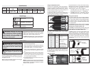
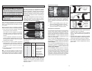
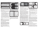
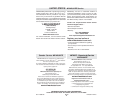
Selecting Speed
Fig. 1
Using the Adjustable Clutch
This tool has an adjustable clutch for driving differ-
ent types of screws into different materials. When
properly adjusted, the clutch will slip at a preset
torque to prevent driving the screw too deep and
to prevent damage to the screw or tool.
To adjust the clutch, turn the clutch adjusting ring
so that the desired setting (1-23) lines up with the
arrow on the motor housing, as shown.
Fig. 2
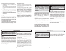
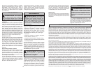
Driving
Drilling
Low = 1
High = 2
Push in
for forward
Fig. 4
Fig. 5
Push in
for reverse
Fig. 3
Fig. 6
Push to
center
position to
lock trigger
Clutch Setting (in. lbs.) Applications
2
4
6
8
10
12
14
16
18
20
22
9.5
10.5
15.5
18.5
22
24.5
28.5
32
35
38.5
56
Small screws in
softwood.
Medium screws in soft-
wood or small screws
in hardwood.
Large screws in
softwoods. Medium
screws in hardwood or
large screws in hard-
wood with pilot hole.
The speed selector is on top of the motor housing.
Allow the tool to come to a complete stop before
changing speeds. See “Applications” for recom-
mended speeds under various conditions.
1. For Low speed (up to 350 RPM), push the
speed selector to the left (“1” is displayed).
2. For High speed (up to 1400 RPM), push the
speed selector to the right (“2” is displayed).
Using Control Switch
The control switch may be set to three positions:
forward, reverse and lock. Due to a lockout mecha-
nism, the control switch can only be adjusted when
the ON/OFF switch is not pressed. Always allow
the motor to come to a complete stop before using
the control switch.
For forward (clockwise) rotation, push in the control
switch from the right side of the tool (Fig. 4). Check
the direction of rotation before use.
For reverse (counterclockwise) rotation, push in the
control switch from the left side of the tool (Fig. 5).
Check direction of rotation before use.
To lock the trigger, push the control switch to the
center position (Fig. 6). The trigger will not work
while the control switch is in the center locked posi-
tion. Always lock the trigger or remove the battery
pack before performing maintenance, changing
accessories, storing the tool and any time the tool
is not in use.
The torque specifications shown here are ap-
proximate values obtained with a fully charged
battery pack.