


4 5
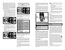
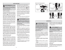
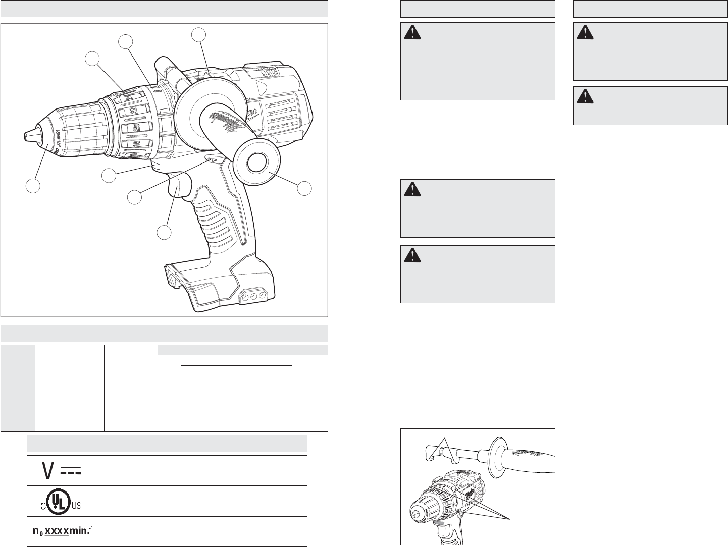
Installing the Side Handle
1. To install the side handle, loosen the
side handle grip until the hooks are far
enough apart to fi t into the slots on the
gear case ring. The side handle can be
positioned on the top, left, or right side
of the tool. Tighten the side handle grip
until it is secure.
2. To remove the side handle, loosen the
side handle grip until the side handle
can be removed. Reposition and tighten
securely.
Symbology
Direct Current
Underwriters Laboratories, Inc.,
United States and Canada
No Load Revolutions per Minute (RPM)
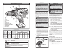
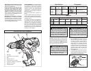
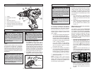
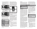
FUNCTIONAL DESCRIPTION
1. Trigger
2. Control switch
3. LED
4. Keyless chuck
5. Torque selector collar
6. Application selector collar
7. Speed selector
8. Side handle
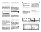
Cat.
No.
2610-20
2611-20
Volts
DC
18
18
Specifi cations
No Load
RPM
Low 0-450
High 0-1800
Low 0-450
High 0-1800
No Load
Blows per
Minute
n/a
Low 0-7200
High 0-28,800
Steel
1/2”
1/2”
Flat
Bit
1-1/2”
1-1/2”
Auger
Bit
1”
1”
Hole
Saw
2-1/8”
2-1/8”
Screws
(dia.)
1/4”
1/4”
Masonry
n/a
5/8”
Capacities
ASSEMBLY
Inserting/Removing Battery Pack
Insert the battery pack by sliding battery
pack into the body of the tool. Insert the
battery pack until the battery latches lock.
To remove the battery pack, press in both
battery latches and slide the battery pack
off of the tool.
OPERATION
Using Keyless Chucks
This tool is equipped with a spindle lock. The
chuck can be tightened with one hand, creat-
ing higher grip strengths on the bit.
Always remove the battery pack or lock the
trigger before inserting or removing bits.
1. To open the chuck jaws, turn the sleeve
in the counterclockwise direction.
When using drill bits, allow the bit to
strike the bottom of the chuck. Center
the bit in the chuck jaws and lift it about
1/16" off of the bottom.
When using screwdriver bits, insert the
bit far enough for the chuck jaws to grip
the hex of the bit.
2. To close the chuck jaws, turn the
sleeve in the clockwise direction. The
bit is secure when the chuck makes a
ratcheting sound and the sleeve can not
be rotated any further.
3. To remove the bit, turn the sleeve in the
counterclockwise direction.
NOTE: A ratcheting sound may be heard
when the chuck is opened or closed. This
noise is part of the locking feature, and
does not indicate a problem with the chuck’s
operation.
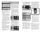
Selecting Speed
The speed selector is on top of the motor
housing. Allow the tool to come to a complete
stop before changing speeds. See “Ap-
plications” for recommended speeds under
various conditions.
1. For Low speed (up to 450 RPM), push
the speed selector to display “1”.
2. For High speed (up to 1800 RPM), push
the speed selector to display “2”.
1
2
8
4
6
7
5
3
Fig. 1
Hooks
Slots
WARNING Recharge only with
the charger specifi ed for the battery.
For specifi c charging instructions, read
the operator’s manual supplied with
your charger and battery. This tool is
not compatible with V™-technology or
NiCd systems.
WARNING Always lock trigger
or remove battery pack before changing
or removing accessories. Only use ac-
cessories specifi cally recommended for
this tool. Others may be hazardous.
WARNING To reduce the risk of
injury, wear safety goggles or glasses
with side shields.
WARNING Always lock trigger
or remove battery pack before changing
or removing accessories. Only use ac-
cessories specifi cally recommended for
this tool. Others may be hazardous.
WARNING To reduce the risk of
injury, always use a side handle when
using this tool. Always brace or hold se-
curely. Ensure side handle is tightened
securely before each use.
Wood