


4
5
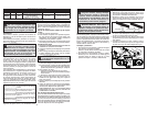
• Hold power tool by insulated gripping sur-
faces, when performing an operation where the
cutting accessory may contact hidden wiring
or its own cord. Cutting accessories contacting
a “live” wire may make exposed metal parts of the
power tool “live” and could give the operator an
electric shock.
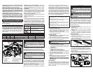
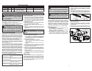
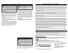
1. Trigger lock
2. Trigger
3. Handle
4. Material guide
FPM
No Load Surface Feet per Minute
Volts Direct Current
Underwriters Laboratories, Inc.,
United States and Canada
SPECIFIC SAFETY RULES
• Use power tools only with specifi cally desig-
nated battery packs. Use of any other battery
packs may create a risk of injury and fi re.
• When battery pack is not in use, keep it away
from other metal objects like paper clips,
coins, keys, nails, screws, or other small metal
objects that can make a connection from one
terminal to another. Shorting the battery termi-
nals together may cause burns or a fi re.
• Under abusive conditions, liquid may be eject-
ed from the battery; avoid contact. If contact
accidentally occurs, fl ush with water. If liquid
contacts eyes, additionally seek medical help.
Liquid ejected from the battery may cause irritation
or burns.
SERVICE
• Have your power tool serviced by a qualifi ed
repair person using only identical replacement
parts. This will ensure that the safety of the power
tool is maintained.
FUNCTIONAL DESCRIPTION
SYMBOLOGY
SPECIFICATIONS
ASSEMBLY
WARNING Recharge only with the
charger specifi ed for the battery. For
specifi c charging instructions, read the opera-
tor’s manual supplied with your charger and
battery.
Inserting/Removing the Battery
To remove the battery, push in the release buttons
and pull the battery pack away from the tool.
To insert the battery, slide the pack into the body of
the tool. Make sure it latches securely into place.
2
1
6
3
4
5
7
8
9
5. Blade
6. Tension lock handle
7. Blade release button
8. Front handle
9. LED ON button
Tool Capacities
Cat. No. Volts FPM Recommended Blades Round Stock Rectangular Stock
2629-20 * 18 DC 480 35-3/8" X 1/2" X .020 Bi-Metal 3-1/4" 3-1/4" x 3-1/4"
* Use only Milwaukee M18 Battery Packs Cat. No. 48-11-1828
• Maintain labels and nameplates. These carry
important information. If unreadable or missing,
contact a MILWAUKEE service facility for a free
replacement.
• WARNING: Some dust created by power sanding,
sawing, grinding, drilling, and other construction
activities contains chemicals known to cause
cancer, birth defects or other reproductive harm.
Some examples of these chemicals are:
• lead from lead-based paint
• crystalline silica from bricks and cement and other
masonry products, and
• arsenic and chromium from chemically-treated
lumber.
Your risk from these exposures varies, depending
on how often you do this type of work. To reduce
your exposure to these chemicals: work in a well
ventilated area, and work with approved safety
equipment, such as those dust masks that are spe-
cially designed to fi lter out microscopic particles.
WARNING Always lock trigger or
remove battery pack before changing or
removing accessories. Only use accessories
specifi cally recommended for this tool. Others
may be hazardous.
Blades and Blade Selection
The blade dimensions required for this band saw
is: .020" thickness, 1/2" width and 35-3/8" in length.
The special .020" thickness reduces fl exure fatigue
and provides maximum tooth life. To maximize cut-
ting life, use a blade with the correct pitch (teeth
per inch) for the specifi c cutting job.
Blades are available in several pitches. To select the
proper blade, three factors should be considered:
The size, shape, and type of material to be cut.
The following suggestions are for selecting the
right blade for various cutting operations. Keep in
mind that these are broad guidelines and that blade
requirements may vary depending upon the specifi c
size, shape and type of material to be cut. Gener-
ally, soft materials require coarse pitch blades and
hard materials require fi ne pitch blades. Use coarse
pitch blades for thick work and fi ne pitch blades for
thin work. It is important to keep at least three teeth
in the cut (see "Typical Application").
• For tough stock 3/16" up to
3-1/4" in diameter or width.
• For tough stock 5/32" to 3/4" in
diameter or width.
• For thin-wall tubing and thin
sheets heavier than 21 gauge.
• For thin-wall tubing and thin
sheets heavier than 21 gauge.
10 Teeth per Inch
14 Teeth per Inch
18 Teeth per Inch
24 Teeth per Inch
Adjusting the 2-Position Material Guide
1. Remove the battery pack.
2. To raise the guide to the upper position, press up
fi rmly to disengage the bottom position detent.
Slide the guide to the upper position.
3. To lower the guide, pull down fi rmly to engage
the bottom-position detent.
Changing Blades
1. REMOVE BATTERY PACK BEFORE CHANG-
ING OR REMOVING BLADES.
2. Raise the material guide to the upper position.
3. Turn the tension lock handle located on the front
of the saw 180° counterclockwise.
Trigger Lock
To lock the trigger, push the Trigger Lock to the
right. The trigger will not work while the switch
is in the locked position. Always lock the trigger
and remove the battery pack before performing
maintenance and when changing accessories.
Lock the trigger when storing the tool and when
the tool is not in use.
Starting and Stopping
1. To start the tool, grasp the handles fi rmly and
pull the trigger.
NOTE: The LED is turned on when the trigger
is pulled.
2. To stop the tool, release the trigger. Allow the tool
to come to a complete stop before removing the
blade from a partial cut or laying the tool down.
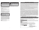
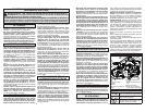
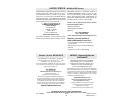
Typical Application
1. Keep the blade off the workpiece until the motor
has reached full speed.
2. Start cutting on a surface where the greatest
number of teeth will be in contact with the work-
piece at one time (Fig 2).
Fig. 2
Correct Incorrect
Fig. 3
WARNING Do not touch blade imme-
diately after use. Blade will be hot.
4. To remove the blade:
a. Pull the blade out of the guides.
b. Then, press the Blade Release Button to lift
the blade above the blade guard and remove
completely.
5. To install a blade:
a. Fit the blade around the pulleys.
NOTE: Be sure the teeth face out.
b. Firmly press the blade between the guides.
6. Turn the tension lock handle 180° clockwise to
secure the blade on the pulleys.
7. Adjust the material guide to the desired
position.
8. Be sure that the blade lies freely within the guard
channel before starting the tool motor.
BE SURE THAT THE BLADE IS PROPERLY
SEATED ON THE PULLEYS BEFORE START-
ING THE CUT.
LED Worklight
The LED worklight is turned on automatically when
the trigger is pulled. To turn on the LED to line-up
a cut or light-up the workpiece, press the LED On
Button. The LED will go off automatically after
about 30 seconds.
OPERATION
WARNING Always remove battery
pack before changing or removing ac-
cessories. Only use accessories specifi cally
recommended for this tool. Others may be
hazardous.
WARNING To reduce the risk of injury,
wear safety goggles or glasses with side
shields.Keep hands away from the blade and
all moving parts.
3. Place the material guide against the workpiece
and lower the moving saw blade into the cut.
4. Do not bear down while cutting. The weight of
the tool will supply adequate pressure for the
fastest cutting.
5. When completing a cut, hold the tool fi rmly so it
will not fall against the workpiece (Fig. 3).