


4
5
Attaching and Removing Accessories
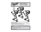
1/2" Impact Wrench with Pin Detent
(Cat. No. 2655-20)
1. Use only the appropriate size Square Drive
Sockets.
2. To attach a socket, align the hole in the acces-
sory with the detent pin on the anvil. Hold the
detent pin in while pushing the socket onto the
anvil. The detent pin will snap into place in the
hole to secure the socket.
3. To remove the socket, insert a nail or other thin
object into the hole in the accessory and press
in the detent pin. Pull the accessory off the anvil.
ASSEMBLY
WARNING Recharge only with the
charger specifi ed for the battery. For specifi c
charging instructions, read the operator’s
manual supplied with your charger and battery.
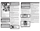
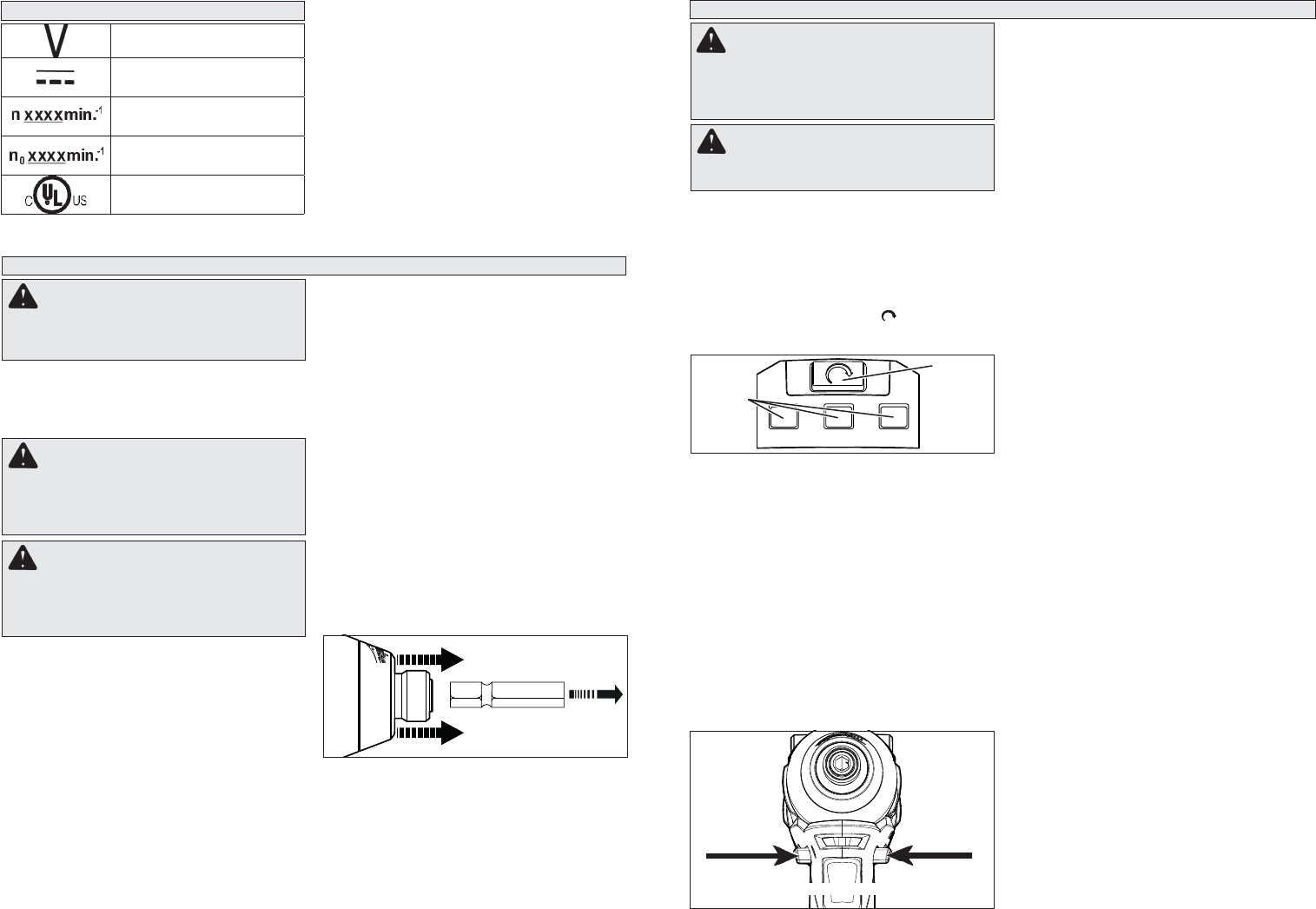
Inserting/Removing the Battery
To remove the battery, push in the release buttons
and pull the battery pack away from the tool.
To insert the battery, slide the pack into the body of
the tool. Make sure it latches securely into place.
WARNING Use only sockets and other
accessories specifi cally designed for use on
impact wrenches and drivers. Other sockets
and accessories might shatter or break caus-
ing injury.
WARNING Always remove battery
pack before changing or removing acces-
sories. Only use accessories specifically
recommended for this tool. Others may be
hazardous.
1/2" Impact Wrench with Ball Detent
(Cat. No. 2655B-20)
1. Use only the appropriate size Square Drive
Sockets.
2. To attach a socket, align the hole in the acces-
sory with the detent ball on the anvil. Push the
socket onto the anvil. The detent ball will snap
into place in the hole to secure the socket.
3. To remove the accessory, pull the accessory
off the anvil.
3/8" Impact Wrench (Cat. No. 2654-20)
1. Use only the appropriate size Square Drive
Sockets.
2. To attach a socket, align the accessory with the
anvil and push it fi rmly over the retaining ring.
3. To remove the accessory, pull the accessory
off the anvil.
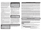
1/4" Hex Impact Driver (Cat. No. 2653-20)
This impact driver is intended for use with drill and
driver bits.
1. To attach an accessory, press the shank into the
hex drive chuck.
2. To remove the accessory, pull out the ring and
remove the accessory. Release the ring.
Starting, Stopping and Controlling Speed
These tools may be operated at any speed from
0 to full speed.
1. To start the tool, pull the trigger.
NOTE: An LED is turned on when the trigger is
pulled.
2. To vary the driving speed, simply increase or
decrease pressure on the trigger. The further
the trigger is pulled, the greater the speed.
3. To stop the tool, release the trigger and the
electric brake stops the tool instantly.
Impacting Techniques
The longer a bolt, screw, or nut is impacted, the
tighter it will become. To help prevent damaging the
fasteners or workpieces, avoid excessive impact-
ing. Be particularly careful when impacting smaller
fasteners because they require less impacting to
reach optimum torque.
Practice with various fasteners, noting the length
of time required to reach the desired torque. Check
the tightness with a hand-torque wrench. If the
fasteners are too tight, reduce the impacting time.
If they are not tight enough, increase the impact-
ing time.
Oil, dirt, rust or other matter on the threads or
under the head of the fastener affects the degree
of tightness.
The torque required to loosen a fastener averages
75% to 80% of the tightening torque, depending on
the condition of the contacting surfaces.
On light gasket jobs, run each fastener down to a
relatively light torque and use a hand torque wrench
for fi nal tightening.
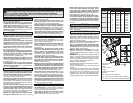
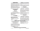
Using the Drive Control
The drive control button is used to adjust the torque,
rotation speed (RPM), and impact speed (IPM) for
the application (see Specifi cations chart for RPM
and IPM).
To select the drive control mode:
1. Pull and release the trigger to turn on the tool.
The current mode indicator is lit.
2. Press the drive control button to cycle through
the 3 modes. When the desired mode indiator
is lit, begin work.
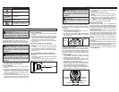
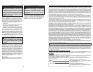
Push for
Forward
Push for
Reverse
PUSH TO CENTER TO LOCK
OPERATION
WARNING Always remove battery
pack before changing or removing acces-
sories. Only use accessories specifically
recommended for this tool. Others may be
hazardous.
WARNING To reduce the risk of injury,
wear safety goggles or glasses with side
shields.
123
Mode
Indicator
Drive
Control
Button
Using the Control Switch
The control switch may be set to three positions:
forward, reverse and lock. Due to a lockout mecha-
nism, the control switch can only be adjusted when
the ON/OFF switch is not pressed. Always allow
the motor to come to a complete stop before using
the control switch.
1. For forward (clockwise) rotation, push the
control switch in the direction shown. Check the
direction of rotation before use.
2. For reverse (counterclockwise) rotation, push
the control switch in the direction shown. Check
the direction of rotation before use.
3. To lock the trigger, push the control switch to the
center position. The trigger will not work when
the control switch is in the locked position.
Always remove the battery pack before perform-
ing maintenance, changing accessories, storing
the tool and any time the tool is not in use.
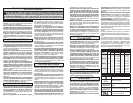
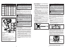
SYMBOLOGY
Volts
Direct Current
Impacts per Minute Under
Load (IPM)
No Load Revolutions per
Minute (RPM)
Underwriters Laboratories, Inc.
United States and Canada