


4
5
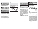
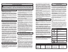
Attaching and Removing Accessories
1/4" Hex Impact Driver (Cat. No. 2667-20)
This impact driver is intended for use with drill and
driver bits with a 1/4" hex shank and ball detent
recess.
1. To attach an accessory, pull the ring out and
insert the shank. Release the ring. It may be
necessary to pull the bit out slightly to engage
the holding mechanism.
2. To remove the accessory, pull out the ring and
remove the accessory. Release the ring.
3/8" Impact Wrench (Cat. No. 2668-20)
1. Use only the appropriate size Square Drive
Sockets.
2. To attach a socket, align the accessory with the
anvil and push it fi rmly over the retaining ring.
3. To remove the accessory, pull the accessory
off the anvil.
ASSEMBLY
WARNING Recharge only with the
charger specifi ed for the battery. For specifi c
charging instructions, read the operator’s
manual supplied with your charger and battery.
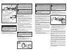
Inserting/Removing the Battery
To remove the battery, push in the release buttons
and pull the battery pack away from the tool.
To insert the battery, slide the pack into the body
of the tool. Make sure it latches securely into place.
WARNING Use only sockets and other
accessories specifi cally designed for use on
impact wrenches and drivers. Other sockets
and accessories might shatter or break caus-
ing injury.
WARNING Always remove battery
pack before changing or removing acces-
sories. Only use accessories specifically
recommended for this tool. Others may be
hazardous.
WARNING To reduce the risk of injury,
securely tighten the drive head screw before
use. Do not use tool with drive head screw
loose or missing.
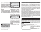
Rotating the Drive Head
To rotate the drive head for a more comfortable grip:
1. Loosen the drive head screw.
2. Pull the drive head away from the tool and rotate
to one of the detent positions.
3. Press the drive head onto the tool and tighten
the drive head screw securely.
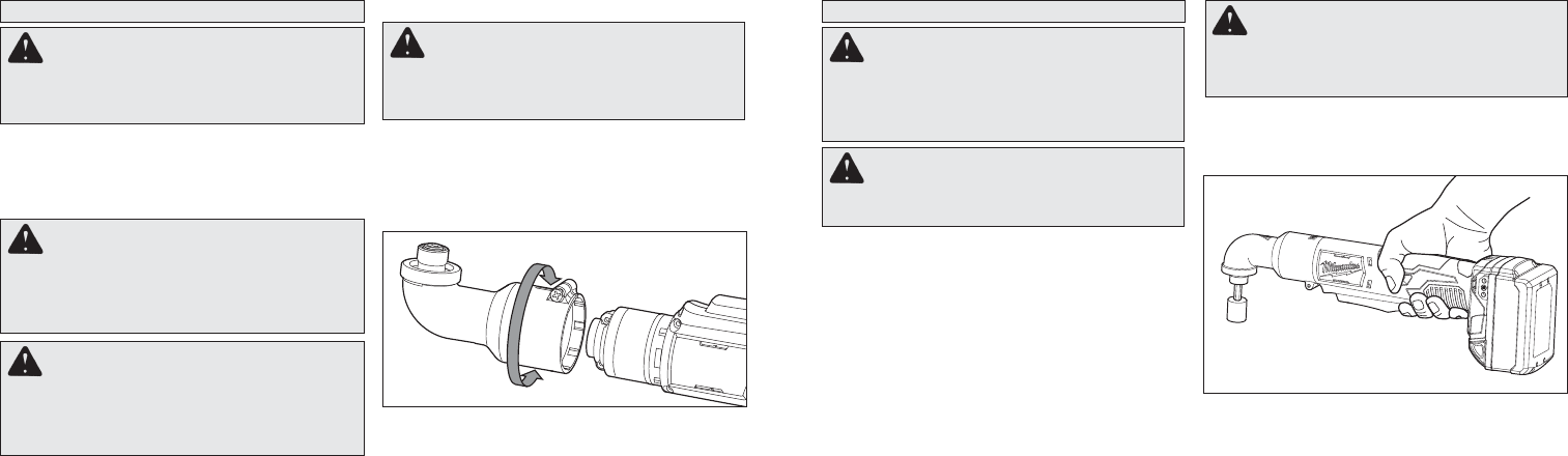
Starting, Stopping and Controlling Speed
1. To start the tool, grasp the tool by the insulated
gripping surface and pull the paddle switch. Keep
hands clear of the drive head.
WARNING To reduce the risk of explo-
sion, electric shock and property damage,
always check the work area for hidden pipes
and wires before drilling.
NOTE: An LED is turned on when the trigger is
pulled.
2. To vary the driving speed, increase or decrease
pressure on the paddle switch. The further the
paddle switch is pulled, the greater the speed.
3. To stop the tool, release the paddle switch.
Impacting Techniques
The longer a bolt, screw, or nut is impacted, the
tighter it will become. To help prevent damaging the
fasteners or workpieces, avoid excessive impact-
ing. Be particularly careful when impacting smaller
fasteners because they require less impacting to
reach optimum torque.
Practice with various fasteners, noting the length of
time required to reach the desired torque. Check the
tightness with a hand-torque wrench. If the fasten-
ers are too tight, reduce the impacting time. If they
are not tight enough, increase the impacting time.
Oil, dirt, rust or other matter on the threads or
under the head of the fastener affects the degree
of tightness.
The torque required to loosen a fastener averages
75% to 80% of the tightening torque, depending on
the condition of the contacting surfaces.
On light gasket jobs, run each fastener down to a
relatively light torque and use a hand torque wrench
for fi nal tightening.
OPERATION
WARNING Always remove battery
pack before changing or removing acces-
sories. Only use accessories specifically
recommended for this tool. Others may be
hazardous.
WARNING To reduce the risk of injury,
wear safety goggles or glasses with side
shields.
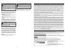
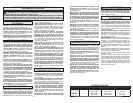
Using the Control Switch
The control switch may be set to three positions:
forward, reverse and lock. Always allow the motor
to come to a complete stop before using the control
switch to avoid damage to the tool.
For forward (clockwise) rotation, push in the control
switch from the right side of the tool ►. Check the
direction of rotation before use.
For reverse (counterclockwise) rotation, push in
the control switch from the left side of the tool ◄.
Check direction of rotation before use.
To lock the trigger, push the control switch to the
center position. The trigger will not work while the
control switch is in the center locked position. Always
lock the trigger or remove the battery pack before
performing maintenance, changing accessories,
storing the tool and any time the tool is not in use.
Selecting Speed
Allow the tool to come to a complete stop before
changing speeds.
1. For Low speed, push the speed selector to
display “1”.
2. For High speed, push the speed selector to
display “2”.