


4
5
ASSEMBLY
WARNING Recharge only with the
charger specifi ed for the battery. For specifi c
charging instructions, read the operator’s
manual supplied with your charger and battery.
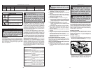
Inserting/Removing the Battery
To remove the battery, push in the release buttons
and pull the battery pack away from the tool.
To insert the battery, slide the pack into the body of
the tool. Make sure it latches securely into place.
WARNING Always lock trigger or
remove battery pack before changing or re-
moving accessories. Only use accessories
specifi cally recommended for this tool. Others
may be hazardous.
Blades and Blade Selection
The blade dimensions required for this band saw
is: .020" thickness, 1/2" width and 44-7/8" in length.
The special .020" thickness reduces fl exure fatigue
and provides maximum tooth life. To maximize cut-
ting life, use a blade with the correct pitch (teeth
per inch) for the specifi c cutting job.
Blades are available in several pitches. To select the
proper blade, three factors should be considered:
The size, shape, and type of material to be cut.
The following suggestions are for selecting the
right blade for various cutting operations. Keep in
mind that these are broad guidelines and that blade
requirements may vary depending upon the specifi c
size, shape and type of material to be cut. Gener-
ally, soft materials require coarse pitch blades and
hard materials require fi ne pitch blades. Use coarse
pitch blades for thick work and fi ne pitch blades for
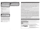
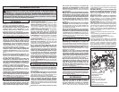
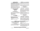
thin work. It is important to keep at least three teeth
in the cut (see "Typical Application").
Changing Blades
1. REMOVE BATTERY PACK BEFORE CHANG-
ING OR REMOVING BLADES.
2. Turn the tension lock handle located on the front
of the saw 180° counterclockwise. This releases
the tension on the blade for easy removal.
3. Remove the blades from the pulley fi rst and then
from the guides.
4. To install a new blade, with the pulleys facing up,
insert the blade between the rollers and the faces
of the guides, making sure that the teeth on the left
side of the tool point towards the rear of the tool.
5. With one hand, hold the blade in place between
the rollers and the guides and use the other hand
to position the blade around the pulleys. Be sure
that the blade lies freely within the guard channel
before starting the tool motor.
6. Turn the tension lock handle 180° clockwise to lock
the position. This will secure the blade on the pulleys.
BE SURE THAT THE BLADE IS PROPERLY
SEATED ON THE PULLEYS BEFORE START-
ING THE CUT.
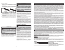
Adjusting the 3-Position Material Guide
1. Remove the battery pack.
2. Press in the guide adjustment button and slide
the material guide to the desired position detent.
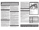
LED Worklight
The LED worklight is turned on automatically
when the trigger is pulled. The LED will go off
automatically.
Fig. 2
OPERATION
WARNING Always remove battery
pack before changing or removing accesso-
ries. Only use accessories specifi cally recom-
mended for this tool. Others may be hazardous.
WARNING To reduce the risk of injury,
wear safety goggles or glasses with side
shields. Keep hands away from the blade and
all moving parts.
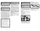
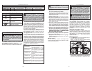
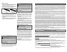
• For tough stock 1/2" to 3-3/8" in
diameter or width (available in
carbon steel only).
• For tough stock 3/8" to 1" in
diameter or width (available in
carbon steel only).
• For tough stock 3/16" up to
4-3/4" in diameter or width.
• For tough stock 5/32" to 3/4" in
diameter or width.
• For thin-wall tubing and thin
sheets heavier than 21 gauge.
• For thin-wall tubing and thin
sheets heavier than 21 gauge.
Fig. 1
6 Teeth per Inch
8 Teeth per Inch
10 Teeth per Inch
14 Teeth per Inch
18 Teeth per Inch
24 Teeth per Inch
Trigger Lock
To lock the trigger, push the Trigger Lock to the
right. The trigger will not work while the switch
is in the locked position. Always lock the trigger
and remove the battery pack before performing
maintenance and when changing accessories.
Lock the trigger when storing the tool and when
the tool is not in use.
Speed Dial
These Band Saws have a speed dial located on
the side of the handle to set the maximum speed.
Rotate the speed dial to “5” for maximum speed,
“1” for minimum speed.
Starting and Stopping
1. To start the tool, grasp both handles fi rmly and
pull the trigger.
NOTE: The LED is turned on when the trigger
is pulled.
WARNING Do not touch blade imme-
diately after use. Blade will be hot.
Fig. 3
Correct Incorrect
Typical Application
1. Keep the blade off of the workpiece until the
motor has reached the selected speed.
2. Start cutting on a surface where the greatest
number of teeth will be in contact with the work-
piece at one time.
3. Place the material guide against the workpiece
and lower the moving saw blade into the cut.
4. Do not bear down while cutting. The weight of
the tool will supply adequate pressure for the
fastest cutting.
5. When completing a cut, hold the tool fi rmly so it
will not fall against the workpiece.
2. To vary the speed, increase or decrease pres-
sure on the trigger. The further the trigger is
pulled, the greater the speed.
3. To stop the tool, release the trigger. Allow the tool
to come to a complete stop before removing the
blade from a partial cut or laying down the tool.