


8 9
WARNING
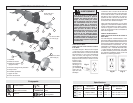
TOOL ASSEMBLY
To reduce the risk of injury,
always unplug tool before at-
taching or removing accessories
or making adjustments. Use only spe-
cifi cally recommended accessories.
Others may be hazardous.
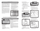
Grinding Wheel Selection
Only use wheels that:
• are high-strength
• are resinoid bond
• are the proper grit
• are the correct size
• are rated at or above the RPM listed on
the tool's nameplate
• have blotters that cover the entire fl ange
contact area.
Care of Grinding Wheels
Grinding wheels should be protected from"
• wetness and extreme humidity
• any type of solvent
• extreme changes in temperature
• dropping and bumping.
Grinding wheels should be stored:
• in an organized way so wheels can be
removed without disturbing or damaging
other wheels
• with their safety information.
Grinding wheels should NOT be:
• dropped
• rolled
• bumped.
If any wheel is dropped, rolled, bumped, sub-
jected to extreme changes in temperature,
or has come into contact with solvents or
wetness, discard wheel immediately.
WARNING
To reduce the risk of injury and dam-
age to the tool, use ONLY accessories
rated at or above the RPM listed on
the tool's nameplate.
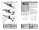
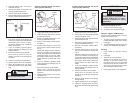
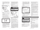
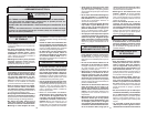
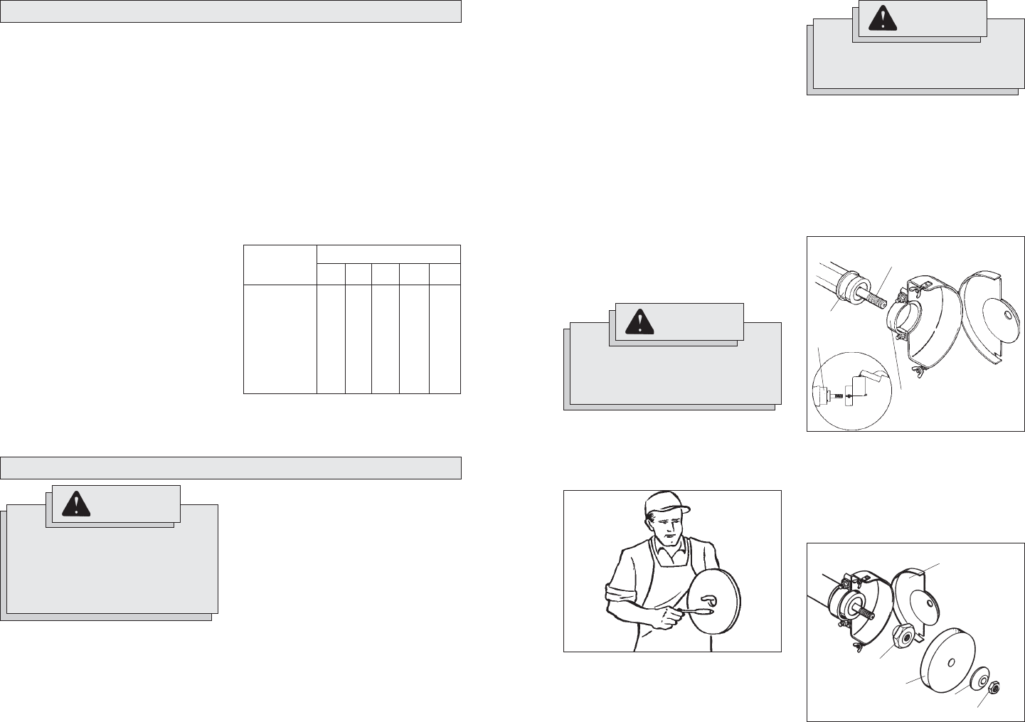
To Test the Wheel:
NOTE: Wheel must be dry to do this test.
1. Suspend the wheel by its arbor hole on
a small pin or a fi nger (Fig. 1).
2. Tap the side of the wheel with the back
of a screwdriver (or any similar, solid,
non-metallic object).
3. Rotate wheel 90° and repeat the test in
three more places.
If the wheel rings, it is in good condition.
If it does not ring, it is bad and should be
discarded.
Fig. 1
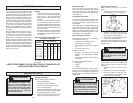
Grounded tools require a three wire exten-
sion cord. Double insulated tools can use
either a two or three wire extension cord.
As the distance from the supply outlet
increases, you must use a heavier gauge
extension cord. Using extension cords with
inadequately sized wire causes a serious
drop in voltage, resulting in loss of power
and possible tool damage. Refer to the table
shown to determine the required minimum
wire size.
The smaller the gauge number of the wire,
the greater the capacity of the cord. For ex-
ample, a 14 gauge cord can carry a higher
current than a 16 gauge cord. When using
more than one extension cord to make up
the total length, be sure each cord contains
at least the minimum wire size required. If
you are using one extension cord for more
than one tool, add the nameplate amperes
and use the sum to determine the required
minimum wire size.
Guidelines for Using Extension Cords
• If you are using an extension cord out-
doors, be sure it is marked with the suffi x
“W-A” (“W” in Canada) to indicate that it
is acceptable for outdoor use.
• Be sure your extension cord is prop-
erly wired and in good electrical
condition. Always replace a damaged
extension cord or have it repaired by a
qualifi ed person before using it.
• Protect your extension cords from sharp
objects, excessive heat and
damp or wet areas.
READ AND SAVE ALL INSTRUCTIONS FOR FUTURE USE.
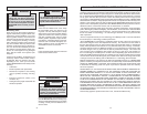
Recommended Minimum Wire Gauge
for Extension Cords*
Extension Cord Length
* Based on limiting the line voltage drop to
fi ve volts at 150% of the rated amperes.
Nameplate
Amperes
0 - 2.0
2.1 - 3.4
3.5 - 5.0
5.1 - 7.0
7.1 - 12.0
12.1 - 16.0
16.1 - 20.0
25'
18
18
18
18
16
14
12
75'
18
18
16
14
12
10
100'
18
16
14
12
10
150'
16
14
12
12
50'
18
18
18
16
14
12
10
EXTENSION CORDS
Grit Selection
The lower the grit number, the coarser the
wheel. Coarser wheels should be used for
rough grinding and fi ner wheels for fi nish
grinding (see "Accessories").
Wheel Material
Grinding wheels are made from various
materials and are meant for different jobs.
Be sure you choose the proper wheel for the
job you plan to do.
MILWAUKEE Straight Grinders use type 1,
straight wheels as defi ned by the American
National Standards Institute (ANSI). Type
1 straight wheels are made to be used for
edge grinding. They are not to be used for
side grinding.
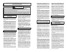
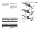
Installing Guard Assemblies
The guards for all tools in this manual are
mounted the same way:
1. Unplug tool and lay it on its tool rest.
2. Loosen guard clamping fasteners.
3. Position guard clamp over the spindle
housing and against the housing shoul-
der (Fig. 2).
Fig. 2
WARNING
To reduce the risk of injury, the wheel
guard must be fl ush with the spindle
housing.
4. Position guard so the operator is always
behind the guard. The open edge of the
guard should face the workpiece.
5. Tighten wheel guard clamps.
Installing Grinding Wheels and Acces-
sories (Cat. No. 5211 only)
Fig. 3
1. Unplug tool and lay it on its tool rest.
2. Loosen wing nuts. Move studs aside and
swing the faceplate away.
Spindle
housing
shoulder
Spindle
Guard clamp
Inner fl ange
Faceplate
Grinding wheel
Outer fl ange
Spindle nut