


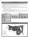

page 5
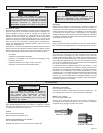
To reduce the risk of injury,
always unplug tool before attaching or remov-
ing accessories. Use only specifically recom-
mended accessories. Others may be
hazardous.
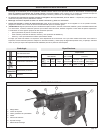
TOOL ASSEMBLY
WARNING!
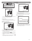
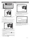
Removing the Chuck (Fig. 1)
1. Hold the chuck firmly and pull back sleeve toward direction of arrow
(1).
2. Chuck pops out of the spindle, hold it firmly (2).
Inserting the Chuck
1. Push chuck into spindle turning until locked into position.
2. Remember to clean and lightly grease the spindle from time to time.
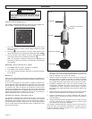
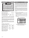
Inserting Drill Bit or Chisel (Fig. 2)
NOTE: Only use accessories with SDS-plus shank.
1. Align the symbol
with dimple on front of chuck.
2. Rotate bit slowly until it aligns with locking mechanism.
3. Push the bit in, turn it slightly until it can be pushed in completely and
you can feel the notch fit into place.
4. Turn the chuck collar so that the symbol
aligns with dimple on
front of the chuck. The tool should now be locked.
5. Check that the bit is locked properly it should be possible to move
it slightly.
6. To remove bits and chisels, turn chuck collar so that the symbol
aligns with dimple on the front of chuck. Remove bit.
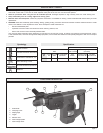
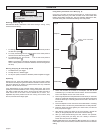
Adjusting the Side Handle Position (Fig. 3)
Fig. 3
Side Handle
Clamping Screw
1. Loosen the clamping screw slightly.
2. Pull the side handle forward and turn it to the required angle.
3. Fit the side handle into the nonslip mounting until it adjusts into place
and retighten the clamping screw.
NOTE: The side handle can be locked in increments of 30 degrees.
Setting the Depth Gauge (Fig. 4)
Fig. 4
Drilling Depth
Fig. 2
Symbol
Dimple
1. Loosen the clamping screw.
2. Slide the depth gauge rod backward or forward until it is set
for the desired depth. NOTE: The drilling depth is the
distance between the tip of the bit and the tip of the depth gauge rod.
3. Tighten the clamping screw securely.
Fig. 1
1
2