


4
5
Grounded tools require a three wire extension
cord. Double insulated tools can use either a two
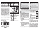
or three wire extension cord. As the distance from
the supply outlet increases, you must use a heavier
gauge extension cord. Using extension cords with
inadequately sized wire causes a serious drop in
voltage, resulting in loss of power and possible tool
damage. Refer to the table shown to determine the
required minimum wire size.
The smaller the gauge number of the wire, the
greater the capacity of the cord. For example, a 14
gauge cord can carry a higher current than a 16
gauge cord. When using more than one extension
cord to make up the total length, be sure each cord
contains at least the minimum wire size required. If
you are using one extension cord for more than one
tool, add the nameplate amperes and use the sum
to determine the required minimum wire size.
Guidelines for Using Extension Cords
• If you are using an extension cord outdoors, be
sure it is marked with the suffi x “W-A” (“W” in
Canada) to indicate that it is acceptable for outdoor
use.
• Be sure your extension cord is properly wired
and in good electrical condition. Always replace a
damaged extension cord or have it repaired by a
qualifi ed person before using it.
• Protect your extension cords from sharp objects,
excessive heat and damp or wet areas.
READ AND SAVE ALL
INSTRUCTIONS FOR FUTURE USE.
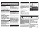
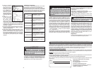
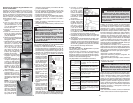
Recommended Minimum Wire Gauge
for Extension Cords*
Extension Cord Length
* Based on limiting the line voltage drop to fi ve volts
at 150% of the rated amperes.
Nameplate
Amperes
0 - 2.0
2.1 - 3.4
3.5 - 5.0
5.1 - 7.0
7.1 - 12.0
12.1 - 16.0
16.1 - 20.0
25'
18
18
18
18
16
14
12
75'
18
18
16
14
12
10
100'
18
16
14
12
10
150'
16
14
12
12
50'
18
18
18
16
14
12
10
EXTENSION CORDS
WARNING To reduce the risk of injury,
always use a side handle when using
this tool. Always brace or hold securely.
ASSEMBLY
WARNING To reduce the risk of injury,
always unplug tool before attaching
or removing accessories or making adjust-
ments. Use only specifi cally recommended
accessories. Others may be hazardous.
Adjusting the Side Handle Position
1. Loosen the side handle by unscrewing the side
handle grip until the side handle rotates freely.
2. Rotate the side handle to the desired position.
3. Tighten the side handle grip securely.
OPERATION
WARNING To reduce the risk of injury,
always unplug tool before attaching
or removing accessories or making adjust-
ments. Use only specifi cally recommended
accessories. Others may be hazardous.
WARNING To reduce the risk of injury,
keep hands and cord away from the
bit and all moving parts.
WARNING To reduce the risk of injury
do not grasp the bit while the chuck is rotat-
ing or while the bit is falling from the chuck.
WARNING To reduce the risk of injury,
wear safety goggles or glasses with
side shields.
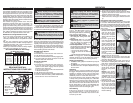
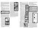
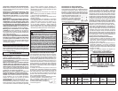
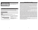
FUNCTIONAL DESCRIPTION
1. Side handle
2. Bit holder
3. Bit release collar
4. Mode selector
knob
5. Trigger
Installing Bits and Chisels
Be sure that the shank of the bit is clean. Dirt par-
ticles may cause the bit to line up improperly. Do not
use bits larger than the maximum recommended
capacity of the drill because gear damage or mo-
tor overloading may result. For best performance,
be sure that the bit is properly sharpened and the
shank is lightly greased before use. Use caution
when handling hot bits and chisels.
SDS-Max Drive System
1. Unplug tool.
2. Insert the bit or chisel into the nose of the tool.
3. Push bit into tool until it locks.
5. Check to see that the bit is locked by tugging on it.
6. To remove bits and chisels, pull back on the bit
release collar and remove bit.
Spline Drive System
1. Unplug tool.
2. Insert the bit or chisel into the nose of the tool.
If you are using a rotary bit, make sure that the
splines on the shank engage with the splines
inside the nose of the tool.
If you are using a chisel, make sure that the notch
in the shank faces up.
3. Push bit into tool until it locks.
4. Check to see that the bit is locked by tugging on it.
5. To remove bits and chisels, pull bit release collar
toward the rear of tool and remove bit.
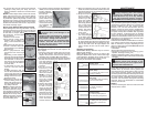
Selecting Action
These MILWAUKEE Rotary
Hammers have three settings:
hammering with rotation, hammering-
only, and chisel adjustment.
1. Hammering with rotation. Use
this setting for drilling holes with
drill bits.
2. Hammering only. For use with
“hammering-only” accessories.
Use this setting for chiseling or
setting self-drilling anchors.
3. Chisel adjustment. Use this set-
ting to adjust the angle of the chisel
blade in relation to the tool. With a
chisel mounted in the tool:
• turn the knob to this setting
• rotate the chisel to the desired
angle
• turn the knob to "hammering-only".
NOTE: To engage the hammering mechanism,
maintain pressure on the bit. When the pressure
on the bit is released, the hammering will stop.
Starting and Stopping
1. To start the tool, grasp the handle fi rmly and pull
the trigger.
2. To stop the tool, release the trigger. Make sure
the tool comes to a complete stop before laying
the tool down.
Operating
Position the tool, grasp the handles fi rmly and pull
the trigger. Always hold the tool securely using both
handles to maintain control. This tool has been
designed to achieve top performance with only
moderate pressure. Let the tool do the work.
If the speed begins to drop off when drilling large
or deep holes, pull the bit partially out of the hole
while the tool is running to help clear dust. Do not
use water to settle the dust since it will clog the bit
fl utes and tend to make the bit bind in the hole. If
the bit should bind, a built-in, non-adjustable slip
clutch prevents the bit from turning. If this occurs,
stop the tool, free the bit and begin again.
Cold Starting
If this tool is stored for a long period of time or
at cold temperatures, it may not hammer ini-
tially because the lubrication has become stiff.
To warm up the tool:
2
1
4
5
1. Insert and lock a bit or chisel into the tool.
2. Pull the trigger and apply force to the bit or chisel
against a concrete or wood surface for a few
seconds. Release the trigger
3. Repeat until the tool starts hammering. The
colder the tool is, the longer it will take to warm
up.
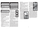
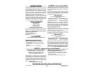
Using Rotary Percussion Core Bits
Core Bits are useful for drilling large or long holes
in concrete. MILWAUKEE Heavy-Duty Core Bits
have heat-treated steel bodies with durable carbide
tips. These core bits are specially designed for fast,
accurate drilling with combined hammering and
rotary action.
1. Clean and lubricate the
threads on the adapter
and core bit to make
later removal easier.
Thread the adapter
shank to the rear of the
core bit.
2. Push the guide plate
onto the pointed end
of the center pin. In-
sert the center pin and
guide plate assembly
into the core bit. Be
sure the small end of
the center pin is se-
curely placed into the
hole in the center of the
core bit.
For LHS systems, screw the threaded end of the
centering bit into the core bit.
NOTE: If using an extension, fi rst thread the
adapter shank to the extension. Then thread the
core bit to the extension.
3. Insert the adapter into the nose of the tool as
described in “Installing Bits and Chisels”. Set the
knob to the "hammering with rotation" setting.
4. Press the centering
bit fi rmly against your
center mark, hold the
tool fi rmly and pull the
trigger.
NOTE: If the 48-20-
5099 threaded stud is
used, or a center pin
and guide plate are not
available, use a tem-
plate or notched board
to start the hole.
5. Start the tool. After drill-
ing to about the depth
of the core bit teeth,
remove the center pin
and guide plate from
the core bit (not nec-
esary for LHS system).
Resume drilling.
3