


18
19
• Wear ear protectors. Exposure to noise can
cause hearing loss.
• Use auxiliary handle(s), if supplied with the
tool. Loss of control can cause personal injury.
• Hold power tools by insulated gripping surfaces,
when performing an operation where the cutting
tool may contact hidden wiring or its own cord.
Cutting accessory contacting a “live” wire may make
exposed metal parts of the power tool “live” and
could give the operator an electric shock.
• Keep hands away from all cutting edges and
moving parts.
• Maintain labels and nameplates. These carry
important information. If unreadable or missing,
contact a MILWAUKEE service facility for a free
replacement.
• WARNING: Some dust created by power sanding,
sawing, grinding, drilling, and other construction
activities contains chemicals known to cause can-
cer, birth defects or other reproductive harm. Some
examples of these chemicals are:
• lead from lead-based paint
• crystalline silica from bricks and cement and other
masonry products, and
• arsenic and chromium from chemically-treated
lumber.
Your risk from these exposures varies, depending
on how often you do this type of work. To reduce
your exposure to these chemicals: work in a well
ventilated area, and work with approved safety
equipment, such as those dust masks that are spe-
cifi cally designed to fi lter out microscopic particles.
SPECIFIC SAFETY RULES
SYMBOLOGY
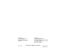
Volts
Alternating Current
IPM
Blows per Minute (BPM)
No Load Revolutions per
Minute (RPM)
Seal of Electrical Security
Read operator's manual
Wear hearing protection
Wear eye protection
Grounded tools require a three wire extension
cord. Double insulated tools can use either a two
or three wire extension cord. As the distance from
the supply outlet increases, you must use a heavier
gauge extension cord. Using extension cords with
inadequately sized wire causes a serious drop in
voltage, resulting in loss of power and possible tool
damage. Refer to the table shown to determine the
required minimum wire size.
The smaller the gauge number of the wire, the
greater the capacity of the cord. For example, a 14
gauge cord can carry a higher current than a 16
gauge cord. When using more than one extension
cord to make up the total length, be sure each cord
contains at least the minimum wire size required.
If you are using one extension cord for more than
one tool, add the nameplate amperes and use the
sum to determine the required minimum wire size.
Guidelines for Using Extension Cords
• If you are using an extension cord outdoors, be
sure it is marked with the suffi x “W-A” (“W” in Cana-
da) to indicate that it is acceptable for outdoor use.
• Be sure your extension cord is properly wired
and in good electrical condition. Always replace a
damaged extension cord or have it repaired by a
qualifi ed person before using it.
• Protect your extension cords from sharp objects,
excessive heat and damp or wet areas.
READ AND SAVE ALL
INSTRUCTIONS FOR FUTURE USE.
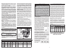
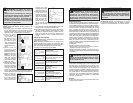
* Based on limiting the line voltage drop to fi ve volts at
150% of the rated amperes.
EXTENSION CORDS
Recommended Minimum Wire Gauge
or Extension Cords*
Nameplate
Amperes
Extension Cord Length
25' 50' 75' 100' 150'
0 - 2.0
2.1 - 3.4
3.5 - 5.0
5.1 - 7.0
7.1 - 12.0
12.1 - 16.0
16.1 - 20.0
18
18
18
18
16
14
12
18
18
18
16
14
12
10
8
18
16
14
12
10
--
18
16
14
12
10
--
--
16
14
12
12
--
--
--
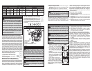
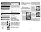
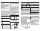
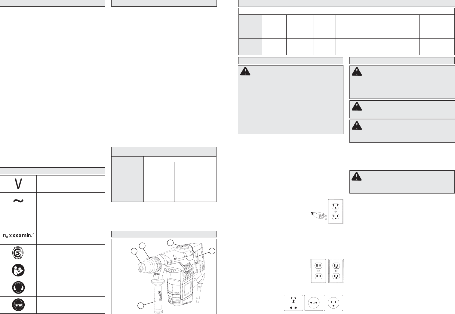
1. Side handle
2. Bit holder
3. Bit release collar
4. Mode selector
knob
5. Trigger
2
1
4
5
3
FUNCTIONAL DESCRIPTION
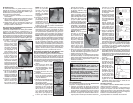
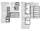
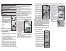
Grounded Tools: Tools with Three Prong Plugs
Tools marked “Grounding Required” have a three
wire cord and three prong grounding plug. The
plug must be connected to a properly grounded
outlet (See Figure A). If the tool should electrically
malfunction or break down, grounding provides a
low resistance path to carry electricity away from
the user, reducing the risk of electric shock.
The grounding prong in the plug is connected through
the green wire inside the cord to the grounding
system in the tool. The green wire in the cord must
be the only wire connected to the tool's grounding
system and must never be attached to an electrically
“live” terminal. Your tool must be
plugged into an appropriate outlet,
properly installed and grounded
in accordance with all codes and
ordinances. The plug and outlet
should look like those in Figure A.
Double Insulated Tools: Tools
with Two Prong Plugs
Tools marked “Double Insulated” do not require
grounding. They have a special double insulation
system which satisfi es OSHA requirements and com-
plies with the applicable standards of Underwriters
Laboratories, Inc., the Canadian
Standard Association and the Na-
tional Electrical Code. Double In-
sulated tools may be used in either
of the 120 volt outlets shown in
Figures B and C.
In specific countries, double
insulated tools could
be used in the output
connections suitable
for the plug.
Fig. B
Fig. C
Fig. A
GROUNDING
WARNING Improperly connecting the
grounding wire can result in the risk of elec-
tric shock. Check with a qualifi ed electrician
if you are in doubt as to whether the outlet is
properly grounded. Do not modify the plug
provided with the tool. Never remove the
grounding prong from the plug. Do not use
the tool if the cord or plug is damaged. If
damaged, have it repaired by a MILWAUKEE
service facility before use. If the plug will not
fi t the outlet, have a proper outlet installed by
a qualifi ed electrician.
SPECIFICATIONS
Tool Capacities
Cat. No.
Volts AC Hertz W
No Load
RPM BPM Twist bit Core bit Tunnel bit
5317-59
5317-59A
220-240
220-240
50-60
50-60
1100
1100
450
450
3000
3000
40 mm (1-9/16")
40 mm (1-9/16")
102 mm (4")
102 mm (4")
67 mm (2-5/8")
67 mm (2-5/8")
5347-59
5347-59A
5347-59B
220-240
220-240
127
50-60
50-60
50-60
1100
1100
1100
-
-
-
3 000
3 000
3 000
-
-
-
-
-
-
-
-
-
WARNING To reduce the risk of injury,
always use a side handle when using this tool.
Always brace or hold securely.
Adjusting the Side Handle Position
1. Loosen the side handle by unscrewing the side
handle grip until the side handle rotates freely.
2. Rotate the side handle to the desired position.
3. Tighten the side handle grip securely.
WARNING To reduce the risk of injury
do not grasp the bit while the chuck is rotat-
ing or while the bit is falling from the chuck.
Installing Bits and Chisels
Be sure that the shank of the bit is clean. Dirt par-
ticles may cause the bit to line up improperly. Do not
use bits larger than the maximum recommended
capacity of the drill because gear damage or mo-
tor overloading may result. For best performance,
be sure that the bit is properly sharpened and the
shank is lightly greased before use. Use caution
when handling hot bits and chisels.
SDS-Max Drive System
1. Unplug tool.
2. Insert the bit or chisel into the nose of the tool.
3. Push bit into tool until it locks.
4. Check to see that the bit is locked by tugging on it.
5. To remove bits and chisels, pull back on the bit
release collar and remove bit.
ASSEMBLY
WARNING To reduce the risk of injury,
always unplug tool before attaching or remov-
ing accessories or making adjustments. Use
only specifi cally recommended accessories.
Others may be hazardous.
WARNING To reduce the risk of injury,
wear safety goggles or glasses with side shields.