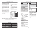
8 9
WARNING
To reduce the risk of injury, wear
safety goggles or glasses with side
shields. Unplug the tool before
changing accessories or making
adjustments.
OPERATION
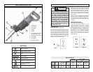
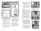
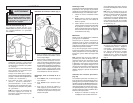
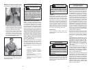
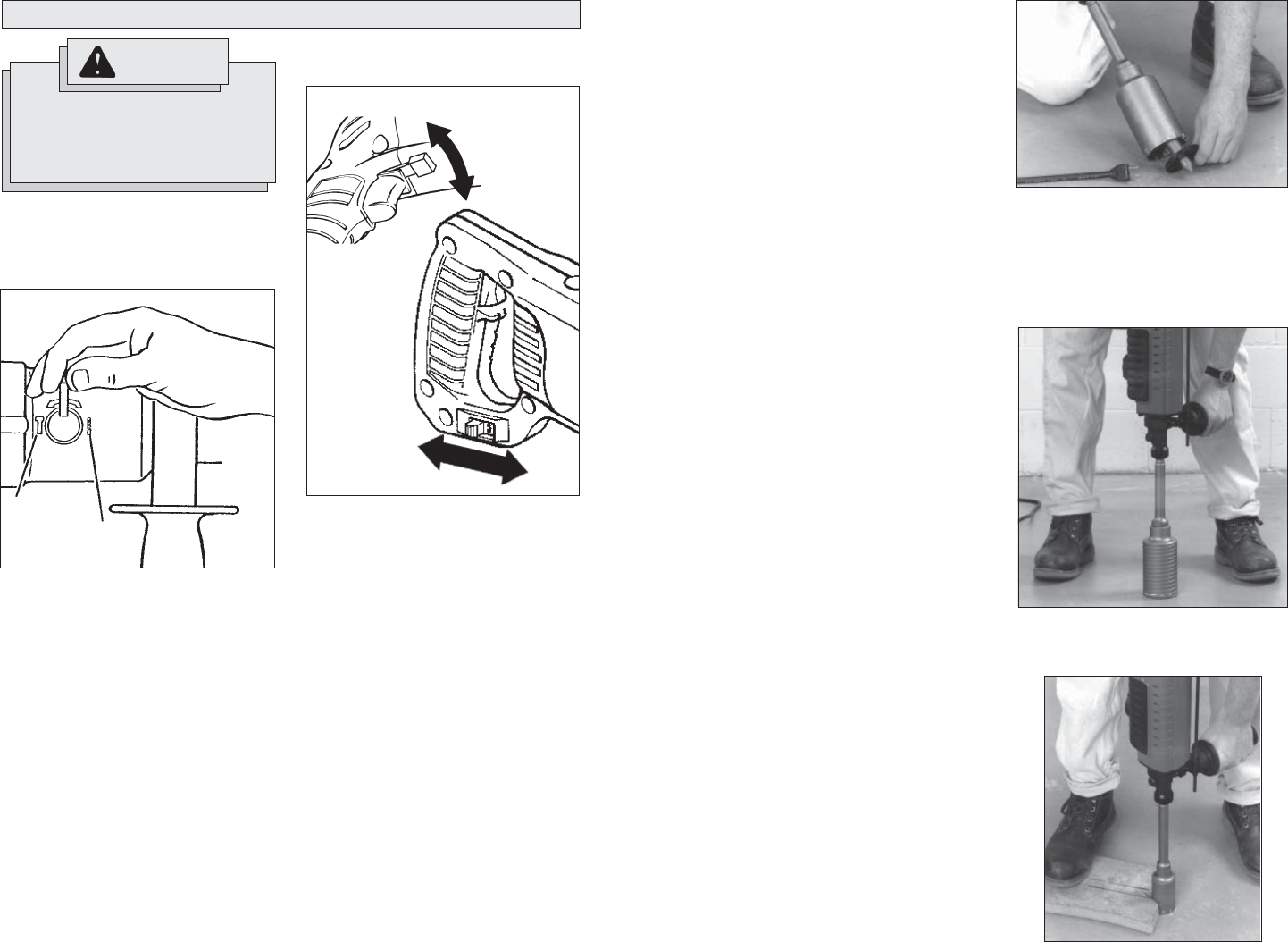
Selecting Action (Fig. 3)
MILWAUKEE 7/8" Rotary Hammers have
two settings: drilling only and hammering
with rotation.
1. To select drilling only, rotate the shift
knob 180° in the direction of the double
arrow so that the tab portion of the knob
points toward the “Drill” symbol. Do not
shift the tool when it is running or coast-
ing to a stop.
When drilling in wood or steel, shift knob
to drilling and use chuck adapter kit (see
“Accessories”).
2. To select hammering with rotation, rotate
the shift knob 180° in the direction of the
double arrow so that the tab portion of
the knob points toward the “Hammer”
symbol.
NOTE: To engage the hammering
mechanism, maintain pressure on
the bit. When pressure on the bit is
released, the hammering action will
stop.
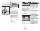
1. For forward (clockwise) rotation, push
the forward/reverse switch to forward
as shown.
2. For reverse (counterclockwise) rota-
tion, push the forward/reverse switch to
reverse as shown. Check the direction
of rotation beofre use. Although an in-
terlock prevents Using forward/reverse
switch (Fig. 4) Check the direction of
rotation before use. Although an inter-
lock prevents reversing the tool while
the motor is running, allow the motor to
come to a full stop before reversing.
Starting, Stopping & Controlling Speed
1. To start the tool, pull the trigger
2. To stop the tool, release the trigger.
3. To vary the driving speed, simply in-
crease or decrease pressure on the
trigger. The further the trigger is pulled,
the greater the speed.
Hammer
symbol
Fig. 3
Drill
symbol
Fig. 4
Forward
Reverse
Forward
Reverse
Using the Forward/Reverse Switch (Fig. 4)
Cold Starting
If this tool is stored for a long period of time
or at cold temperatures, it may not hammer
initially because the lubrication has become
stiff. To warm up the tool:
1. Insert and lock a bit into the tool.
2. Turn the tool on, applying force to the bit
against a concrete or wood surface.
3. Turn the tool on and off every few sec-
onds. In a short time, the tool will start
hammering. The colder the tool is, the
longer it will take to warm it up.
Operation
Position the tool, grasp the handles fi rmly
and pull the trigger.
Always hold the tool securely using both
handles and maintain control. Use only
enough pressure to hold the tool in place
and prevent the tip of the bit from wandering.
This tool has been designed to achieve top
performance with only moderate pressure.
Let the tool do the work.
If the speed begins to drop off when drilling
deep holes, pull the bit partially out of the hole
while the tool is running to help clear dust.
NOTE: Do not use water to settle the dust
since it will clog the bit fl utes and tend to
make the bit bind in the hole. If the bit should
bind, a built-in, non-adjustable slip clutch pre-
vents the bit from turning. If this occurs, stop
the tool, free the bit and begin again.
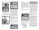
Fig. 7
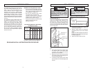
Using Rotary Percussion Core Bits (Fig.
5 - 8)
Core bits are useful for drilling larger holes
for conduit and pipe. MILWAUKEE Thin Wall
Core Bits have heat-treated steel bodies with
durable carbide tips. These core bits are spe-
cially designed for fast, accurate drilling with
combined hammering and rotary action.
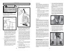
1. Clean and lubricate the threads on
the adapter and core bit to make later
removal easier. Screw the threaded end
of the adapter into the rear of the core
bit.
NOTE: For core bits 1- 1/4" and larger,
push the guide plate onto the pointed
end of the center pin. Insert the center
pin and guide plate assembly into the
core bit. Be sure the small end of the
center pin is securely placed into the
hole in the center of the core bit (Fig. 5).
2. Insert the adapter into the nose of the
tool as described in “Installing Bits”. Set
the hammer/drill shift knob to hammer-
ing with rotation.
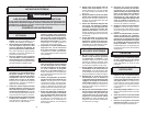
3. Press the center pin fi rmly against your
center mark, hold the tool fi rmly and pull
the trigger (Fig. 6).
NOTE: If a center pin and guide plate are
not available, use a template or notched
board to start the hole (Fig. 7).
Fig. 5
Fig. 6


