


8 9
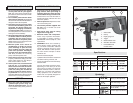
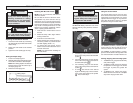
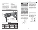
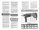
Adjusting the Side Handle Position
1. Loosen the side handle by unscrewing
the side handle grip until the side handle
rotates freely.
2. Rotate the side handle to the desired
position.
3. Tighten the side handle grip securely.
Fig. 1
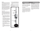
Drilling Depth
Setting the Depth Gauge
1. Press in the clamping lever.
2. Slide the depth gauge rod backward or for-
ward until it is set for the desired depth.
NOTE: The drilling depth is the distance
between the tip of the bit and the tip of
the depth gauge rod.
3. Release the clamping lever.
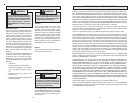
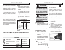
TOOL ASSEMBLY
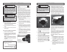
Fig. 23
Release collar
Installing Drill Bits and Chisels
NOTE: Only use accessories with SDS or
SDS Plus shanks.
Be sure that the shank of the bit is clean.
Dirt particles may cause the bit to line up
improperly. Do not use bits larger than the
maximum recommended capacity of the drill
because gear damage or motor overloading
may result. For best performance, be sure
that the bit is properly sharpened and the
shank is lightly greased before use.
1. Insert the bit or chisel into the nose of
the tool.
2. Rotate bit slowly until it aligns with the
locking mechanism.
3. Push bit into tool until it locks.
4. Check that the bit is locked properly; it
should be possible to pull the bit back
and forth slightly (about 1/4”).
5. To remove bits and chisels, pull bit
holder release collar toward the rear of
tool and remove bit.
NOTE: Use caution when handling hot
bits and chisels.
WARNING
To reduce the risk of injury, always
unplug tool before attaching or
removing accessories or making
adjustments. Use only specifi cally
recommended accessories. Others
may be hazardous.
WARNING
To reduce the risk of injury, always
use a side handle when using this
tool. Always brace or hold securely.
WARNING
To reduce the risk of injury, keep
hands away from the bit and all mov-
ing parts. Always wear safety goggles
or glasses with side shields.
OPERATION
Starting, Stopping and Controlling Speed
1. To start the tool, grasp the handle fi rmly
and pull the trigger.
2. To vary the speed, increase or decrease
the pressure on the trigger. The further
the trigger is pulled, the greater the
speed.
3. To stop the tool, release the trigger.
Make sure the tool comes to a complete
stop before laying the tool down.
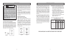
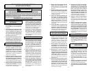
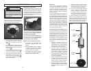
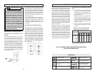
1. For drilling, turn the selector lever so the
arrow on the lever points to the twist drill
symbol .
2. For rotary hammering, turn the selector
lever so the arrow points to the hammer
and twist drill symbol .
3. For hammering only, turn the selector
lever so the arrow points to the hammer
symbol .
4. To freely rotate the bit to the desired
angle for chiseling only, turn the selector
lever so the arrow points to the symbol
. Then, follow step 3.
Selecting Action
MILWAUKEE Rotary Hammers have three
settings: drill only, rotary hammer, and ham-
mer only.
O
Fig. 3
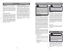
Using the Control Switch
The control switch may be set to two posi-
tions: forward and reverse. Due to a lockout
mechanism, the control switch can only be
adjusted when the trigger is not pulled. Al-
ways allow the motor to come to a complete
stop before using the control switch.
For forward (clockwise) rotation, push the
control switch to the left side of the tool.
Check the direction of rotation before use.
For reverse (counterclockwise) rotation,
push the control switch to the right side of the
tool. Check direction of rotation before use.
Forward
Reverse
Fig. 4