


4
5
Grounded tools require a three wire extension
cord. Double insulated tools can use either a two
or three wire extension cord. As the distance from
the supply outlet increases, you must use a heavier
gauge extension cord. Using extension cords with
inadequately sized wire causes a serious drop in
voltage, resulting in loss of power and possible tool
damage. Refer to the table shown to determine the
required minimum wire size.
The smaller the gauge number of the wire, the
greater the capacity of the cord. For example, a 14
gauge cord can carry a higher current than a 16
gauge cord. When using more than one extension
cord to make up the total length, be sure each cord
contains at least the minimum wire size required.
If you are using one extension cord for more than
one tool, add the nameplate amperes and use the
sum to determine the required minimum wire size.
Guidelines for Using Extension Cords
• If you are using an extension cord outdoors,
be sure it is marked with the suffi x “W-A” (“W”
in Canada) to indicate that it is acceptable for
outdoor use.
• Be sure your extension cord is properly wired
and in good electrical condition. Always replace
a damaged extension cord or have it repaired by
a qualifi ed person before using it.
• Protect your extension cords from sharp objects,
excessive heat and damp or wet areas.
READ AND SAVE ALL
INSTRUCTIONS FOR FUTURE USE.
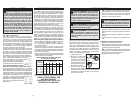
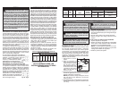
Recommended Minimum Wire Gauge
for Extension Cords*
Extension Cord Length
* Based on limiting the line voltage drop to fi ve volts
at 150% of the rated amperes.
Nameplate
Amperes
0 - 2.0
2.1 - 3.4
3.5 - 5.0
5.1 - 7.0
7.1 - 12.0
12.1 - 16.0
16.1 - 20.0
25'
18
18
18
18
16
14
12
75'
18
18
16
14
12
10
100'
18
16
14
12
10
150'
16
14
12
12
50'
18
18
18
16
14
12
10
EXTENSION CORDS
SPECIFICATIONS
Tool Capacities
Cat. No.
Volts
AC A No Load RPM
No Load
BPM
Drill Only Hammer-Drill
Twist Drill
Bit (Wood)
Twist Drill
Bit (Steel)
Carbide Tipped
Percussion Bit (concrete)
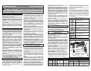
5375-20 120 7.5 0 - 2700 0 - 51,000 1/2" 5/8" 3/4"
WARNING To reduce the risk of injury,
always use a side handle when using
this tool. Always brace or hold securely.
ASSEMBLY
WARNING To reduce the risk of injury,
always unplug tool before attaching
or removing accessories or making adjust-
ments. Use only specifi cally recommended
accessories. Others may be hazardous.
Adjusting the Side Handle Position
1. Loosen the side handle by unscrewing the side
handle grip until the side handle rotates freely.
2. Rotate the side handle to the desired position.
3. Tighten the side handle grip securely.
Setting the Depth Gauge
1. Press in the clamping lever.
2. Slide the depth gauge rod backward or forward
until it is set for the desired depth.
NOTE: The drilling depth is the distance between
the tip of the bit and the tip of the rod.
3. Release the clamping lever.
OPERATION
WARNING To reduce the risk of injury,
always unplug tool before attaching or remov-
ing accessories or making adjustments. Use
only specifi cally recommended accessories.
Others may be hazardous.
WARNING To reduce the risk of injury,
keep hands and cord away from the bit and
all moving parts.
WARNING To reduce the risk of injury
do not grasp the bit while the chuck is rotat-
ing or while the bit is falling from the chuck.
WARNING To reduce the risk of injury,
wear safety goggles or glasses with side
shields.
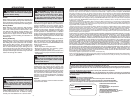
3. Place the chuck key into
each of the three holes
in the chuck, turning it
clockwise to tighten the
chuck securely.
NOTE: Never use a
wrench or means other
than a chuck key to tight-
en or loosen the chuck.
4. To remove the bit, insert
the chuck key into one of the holes in the chuck
and turn it counterclockwise.
Selecting Action
MILWAUKEE Hammer-Drills have two settings:
drilling and hammer-drilling.
1. For drilling, turn the hammer-drill lever towards
the drill symbol
.
2. For hammer-drilling, turn the hammer-drill lever
towards the hammer symbol .
NOTE: To engage the hammering mechanism,
maintain pressure on the bit. When pressure on
the bit is released, the hammering action will stop.
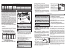
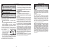
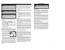
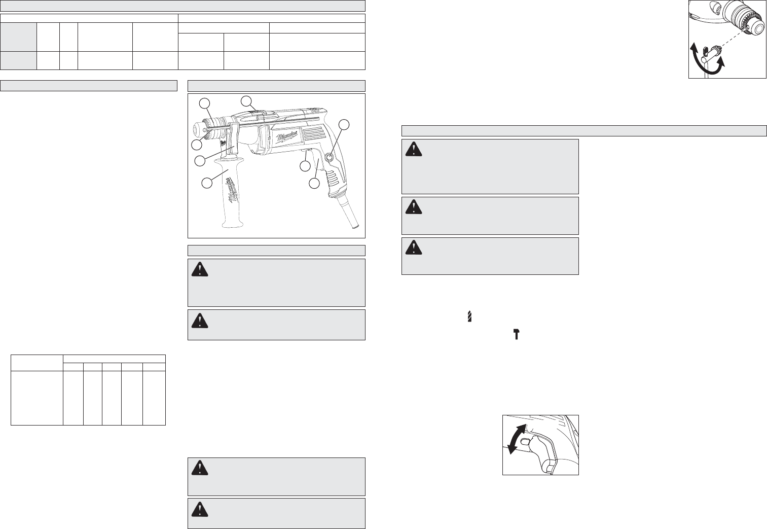
Using Forward/Reverse Lever
The forward/reverse lever can only be adjusted
when the trigger is not pressed. Always allow the
motor to come to a complete stop before using the
forward/reverse lever.
1. For forward (clockwise)
rotation, push the for-
ward/reverse lever to the
left (when viewed from
the back of the tool) as
shown.
2. For reverse (counter-
clockwise) rotation, push
the forward/reverse lever to the right (when
viewed from the back of the tool) as shown. Allow
the motor to come to a full stop before reversing.
NOTE: When hammer-drilling, use the tool in for-
ward rotation (clockwise) only.
Forward
Reverse
Starting, Stopping & Controlling Speed
1. To start the tool, pull trigger.
2. To stop the tool, release trigger.
3. To vary the speed, increase or decrease pres-
sure to trigger. The further the trigger is pulled,
the greater the speed.
Locking Trigger
The lock button holds the trigger in the ON position
for continuous full speed use.
1. To lock the trigger, hold in the lock button while
pulling the trigger. Release the trigger.
2. To unlock the trigger, pull the trigger and release.
The lock button will pop out.
Operating
Position the tool, grasp the handles fi rmly and pull
the trigger. Always hold the tool securely using
both handles and maintain control. This tool has
been designed to achieve top performance with
only moderate pressure. Let the tool do the work.
If the speed begins to drop off when drilling deep
holes, pull the bit partially out of the hole while the
tool is running to help clear dust. Do not use wa-
ter to settle the dust since it will clog the bit fl utes
and tend to make the bit bind in the hole. If the bit
should bind, a built-in, non-adjustable slip clutch
activates. If this occurs, stop the tool, free the bit
and begin again.
Operator Force
This hammer-drill features the Vibration Isolation
System to provide the operator with comfort without
sacrifi cing power or performance. The motor hous-
ing is suspended independently from the switch
handle. Insulating elements absorb vibration when
hammer-drilling and drilling.
Ideal operator force compresses the handle
slightly and allows the tool to work aggressively
while the handle provides maximum vibration
dampening.
Excessive operator force compresses the handle
too far and reduces the vibration dampening. Users
will be able to feel the difference and should adjust
the force to the handle accordingly.
WARNING To prevent personal injury,
always remove the chuck key from the
chuck after each use.
Installing Bits into Keyed Chucks
Be sure that the shank of the bit and the chuck
jaws are clean. Dirt particles may cause the bit
to line up improperly. Do not use bits larger than
the maximum recommended capacity of the drill
because gear damage or motor overloading may
result. For best performance, be sure that the bits
are properly sharpened before use.
1. Unplug the tool.
2. Open the chuck jaws wide enough to insert a bit.
Allow the bit to strike the bottom of the chuck.
Center the bit in the chuck jaws and tighten the
jaws by hand to align the bit.
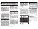
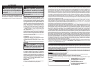
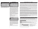
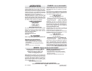
FUNCTIONAL DESCRIPTION
1. Side handle
2. Clamping lever
3. Depth gauge
4. Chuck
5. Hammer/Drill lever
6. Lock button
7. Trigger
8. Forward/Reverse lever
2
1
3
4
5
7
6
8
Loosen
Tighten