


+
-
+
+
-
-
+
-
-
-
-
1
2
2
1
1
2
1
2
4
3
4
3
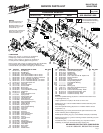
REMOVING THE STEEL QUIK-LOK
®
BLADE CLAMP
• Remove external retaining ring (30) and pull front cam (34) off.
• Pull lock pin (36) out and remove remainder of parts and discard.
REASSEMBLY OF THE STEEL QUIK-LOK
®
BLADE CLAMP
• Coat new lock pin with powdered graphite.
• Hold tool in a vertical position.
• Place spring cover (24) onto spindle.
• Slide torsion spring (31) onto spindle with spring leg on hole side of spindle.
• Slide sleeve (41) onto spindle aligning hole on sleeve with hole in spindle.
• Slide rear cam (35) over sleeve until it bottoms on sleeve shoulder, ensure spring leg inserts into hole in rear cam.
• Rotate rear cam in the direction of the arrows located on spring cover until there is clearance for lock pin (36) to be inserted into sleeve/spindle
holes. Insert lock pin.
• Align front cam (34) inner ribs with rear cam outer slots and slide front cam onto sleeve until it bottoms.
Retaining ring (30) groove should be completely visible.
• Attach retaining ring by separating coils and inserting end of ring into groove, then wind remainder of ring into groove.
Ensure ring is seated in groove.
• Blade clamp should rotate freely. During normal usage, debris may not allow blade clamp to rotate freely. The use of spray lubricant can help free
blade clamp. In extreme conditions, follow these instructions to remove, clean and reassemble blade clamp.
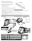
WIRING INSTRUCTIONS
Route carbon brush wires #1 and #2 into
wire traps, as shown.
Carbon brush wires #1 and #2 are to be
positioned with the wire crimps in the traps.
Ensure drill point exists
in bottom of pin hole.
Outer Slot
Leg
36
24
31
41
35
34
30
Terminals, Connectors and 1 or 2 End Wire Preparation
Wire
Color
Origin or
Gauge
Wire
No.
Length
WIRING SPECIFICATIONS
TERMINAL DESCRIPTION
Part No.Code Qnty.
1 Red 22-18-0719 ----- Carbon brush assembly.
2 Black 22-18-1719 ----- Carbon brush assembly.
3 Red 23-94-0015 ----- Leadwire assembly.
4 Black 23-94-0016 ----- Leadwire assembly.
BULK LEAD WIRE - BULLETIN NO. 58-01-0003
WARNING
SWITCH POLARITY SENSITIVE
If wired incorrectly, switch will be
damaged and destroyed!
!
POSITION WIRES ON SWITCH
TABS AND SOLDER,
AS SHOWN.
Place a heavy coat of Type "X"
contact grease, No. 49-08-5000,
in/on terminals of wires #3 and
#4 after installing into connector
block but prior to snapping on
the connector block cover.