PAGE 2 OF 2
BULLETIN NO. 54-43-0040 Jan. 2009
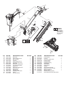
Disassembly:
1, 2, 3, 4, 6 Using a 4 mm hex key, remove hex bolt (1), defl ector (3), muffl er (4), and defl ector pad (2) from top cap (6).
5, 6 Using a 4 mm hex key, remove hex bolts (5) to remove top cap (6).
8, 9, 10, 11, 12, 13 Remove valve assembly (8, 9, 10, 11, 12, and 13) out of the top cap using a 1/8 in. (3.18 mm) punch. Gently push punch
through several different holes in the top of the cap to remove assembly evenly.
14, 19 Remove press ring (14) from the top of cylinder (19) before removing cylinder assembly.
15, 16, 17, 18, 19, 20,
21, 23, 24, 44
Remove driver assembly (15, 16, 17), and cylinder assembly (18, 19, 20, 21, 23, 24) from tool body (44) at the same time
by placing two fl at blade screwdrivers under top ring of cylinder (19), 180° apart, and gently prying the cylinder from the tool
body.
18, 19, 20, 23 Remove cylinder ring (20) from cylinder (19) before removing cylinder spacer assembly (18, 23).
44, 56 74, 77 84 92 Remove magazine assembly (74 and 77) by removing screw (84) from tool body (44) and two screws (92) from magazine/
driver guide (56).
36, 37, 38, 39, 40, 41,
42, 43, 44, 93
Remove trigger valve assembly (93) from tool body (44) by placing a 3/32 in. (2.5 mm) punch inside half moon slot of retainer
(39) and gently tapping shaft of selector (38).Remove spring (42), retainer (39) and ring (43). Remove spring, (41) and trigger
(40) from tool body and push pins (36), and 37) out of tool body (44) just far enough to remove valve assembly. Trigger
valve assembly (93) can be gently pushed out of the tool body from the inside handle area of the tool body using a fl at blade
screwdriver.
Reassembly:
36, 37, 44, 93 Reinstall trigger valve assembly (93) into tool body (44) by aligning the grooves in the valve assembly with the two holes for
spring pins (36 and 37). Drive spring pins into tool body until they are fl ush with the casting surface.
38, 39, 40, 41, 42,
43, 44
Reinstall selection lever assembly (38, 42, 39, 43,) and trigger assembly (40 and 41) by doing the following.
• Place spring (42) onto shaft of selection lever (38).
• Position spring (41) and trigger (40) over plunger of trigger valve assembly (93).
• Insert selection lever assembly (38 and 42) into tool body (44) and align half-moon slot of retainer (39) with half-moon
shaft of selection lever (38) and snap retainer assembly (39 and 43) onto the shaft.
17, 22, 44 Install fl at side of driver guide (22) towards front of tool body (44).
Note: Center opening of driver guide (22) has a fl at side and one with a slight offset to accommodate / help align blade of driver
assembly (17) in the assembly
19, 20, 23, 24 Reinstall cylinder ring (20) onto cylinder (19) only after O-ring (24), and cylinder ring (23) have been installed.
Note: Large fl anged end of cylinder ring (20) must facing the top of cylinder (19) when installed.
15, 16, 17, 18, 19, 20,
21, 22, 23, 44
Assemble driver assembly (15, 16, and 17) and install it into cylinder assembly (18, 19, 20, 21, and 23). Install assembled
components into tool body (44).
Note: Orientation of driver assembly (17) must match orientation of driver guide (22).
6, 14, 19 Reinstall press ring (14) onto top of cylinder (19) with wide edge facing toward top cap (6).
6, 49 Reinstall bumper band (49) into slot on top cap (6).
6, 8, 9, 10, 11, 12, 13 Reinstall spring (8) into internal bore of top cap (6) and snap preassembled head valve assembly (9-13) into top cap.
5, 6, 44 Reinstall top cap assembly (6) onto tool body (44) using hex bolts (5).
Note: To properly seat top cap, tighten the screws at alternating corners a few turns at a time until all screws are secure.
44, 56, 74, 76, 77,
84, 92
Reinstall magazine assembly (74 and 77) onto tool body (44) by securing screw (84) and two screws (92) into magazine/driver
guide (56).
Note: Before completely securing screws (93) make sure magazine channel (76) is aligned properly at the front and rear of
the magazine assembly.
46, 54 Install smooth side of fi lter (54) toward end cap (46).
Apply Blue Loctite
®
242 to fasteners (1), (5), (47) (58), (72) and (92), if removed during disassembly.