


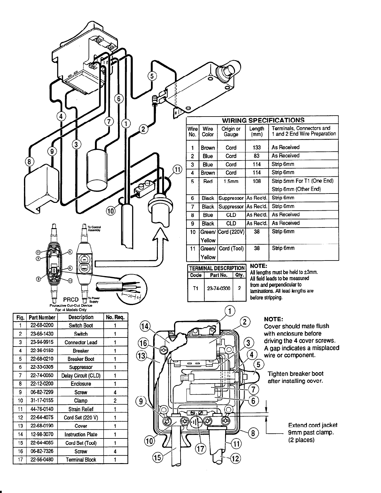
1 and 2 End Wire Preparation
For -4 Models 0th
Fig. Part Number
Description
No. Req.
1 22-68-0200 Switch Boot 1
2 23-66-1430 Switch 1
3
23-94-991s
Connector Lead I
4 22-36-0150 Breaker 1
5 22-68-0210 Breaker Boot 1
6 22-33-030s Suppressor 1
7 22-74-0050 Delay Circuit (CLD) 1
a 22-12-0200 Enclosure 1
9 06-82-7299 Screw 4
IO 31-17-0155 Clamp 2
11 44-76-0140 Strain Relief 1
12 22-64-407s Cord Set (220 V) 1
13 1 22-68-0190 1 Cover 1 1
14 1 12-98-3070 1 Instruction Plate 1 1
15 22-64-4085 Cord Set (Tool) 1
16 06-82-7326 Screw 4
17 22-56-0480 Terminal Block I
I I
I
I
5 1 Red 1 1.5mm 1 108 1 Strip 5mm For
Tl (One End)
6
8
Strip 6mm (Other End)
Strip 6mm
Strip 6mm
As Received
As Received
Strip 6mm
Strip 6mm
NOTE:
All lengths must be held to *3mm.
AU field leads to be measured
from and perpendicular to
laminations. All lead lengths are
before stripping.
NOTE:
Cover should mate flush
with enclosure before
driving the 4 cover screws.
A gap indicates a misplaced
wire or component.
Tighten breaker boot
after installing cover.