


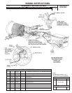
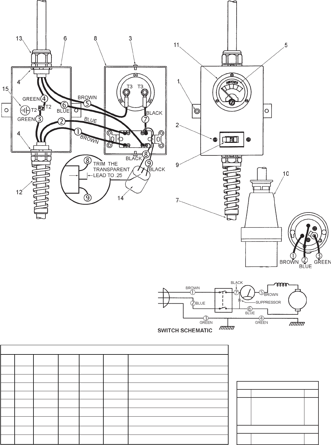
CONNECTOR DESCRIPTION
NOTE:
All leads must be held to ± 1/8".
All lead lengths are before stripping.
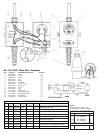
TERMINAL DESCRIPTION
Part No.Code
Qnty.
T1 23-74-0840 1
T2 23-74-0610 2
T3 23-74-0310 2
FIG. PART NO. DESCRIPTION OF PART NO. REQ.
1 06-75-3200 Screw (1)
2 06-81-5660 Screw (2)
3 06-82-5270 Screw (2)
4 06-55-3870 Nut (2)
5 22-04-0030 Meter (1)
6 22-12-0185 Box Body (1)
7 22-64-0195 Power Cord (1)
8 22-68-0175 Box Cover (1)
9 23-66-3030 Switch (1)
10 23-36-3200 Plug (1)
11 31-01-2030 Meter Cover (1)
12 44-76-0185 Cord Strain Relief (1)
13 44-76-0385 Straight Thru Fitting (1)
14 22-33-0030 Suppressor (1)
15 10-98-3030 Ground Label (1)
No. 23-37-0200 Meter Box - Complete
1 Brown Plug Cord 2.5 3.5 Strip both ends .39.
2 Blue Plug Cord 2.2 3.5 Strip both ends .39.
3 Green Plug Cord 2.5 5.5 Strip .19 for T2, Strip the other end .39.
4 Green Motor Cord 4.62 5.5 Strip .19 for T2, Strip .19 for T1.
5 Brown Motor Cord 2.25 3.5 Strip .39 for T3, Strip the other end .39.
6 Blue Motor Cord 2.75 3.5 Strip both ends .39.
7 Black 23-94-4300 4.0 Strip .39 for T3, Strip the other end .39.
8 Black 22-33-0030 Component of the suppressor assy.
9 Black 22-33-0030 Component of the suppressor assy.
Term./Conn. and 1 or 2 End Wire Preparation
Wire
Color
Origin or
Gauge
Wire
No.
Length
Plug End
WIRING SPECIFICATIONS
Length
Box End
Length
Motor End