


4
5
The grounding prong in the plug is connected
through the green wire inside the cord to
the grounding system in the tool. The green
wire in the cord must be the only wire con-
nected to the tool's grounding system and
must never be attached to an electrically
“live” terminal.
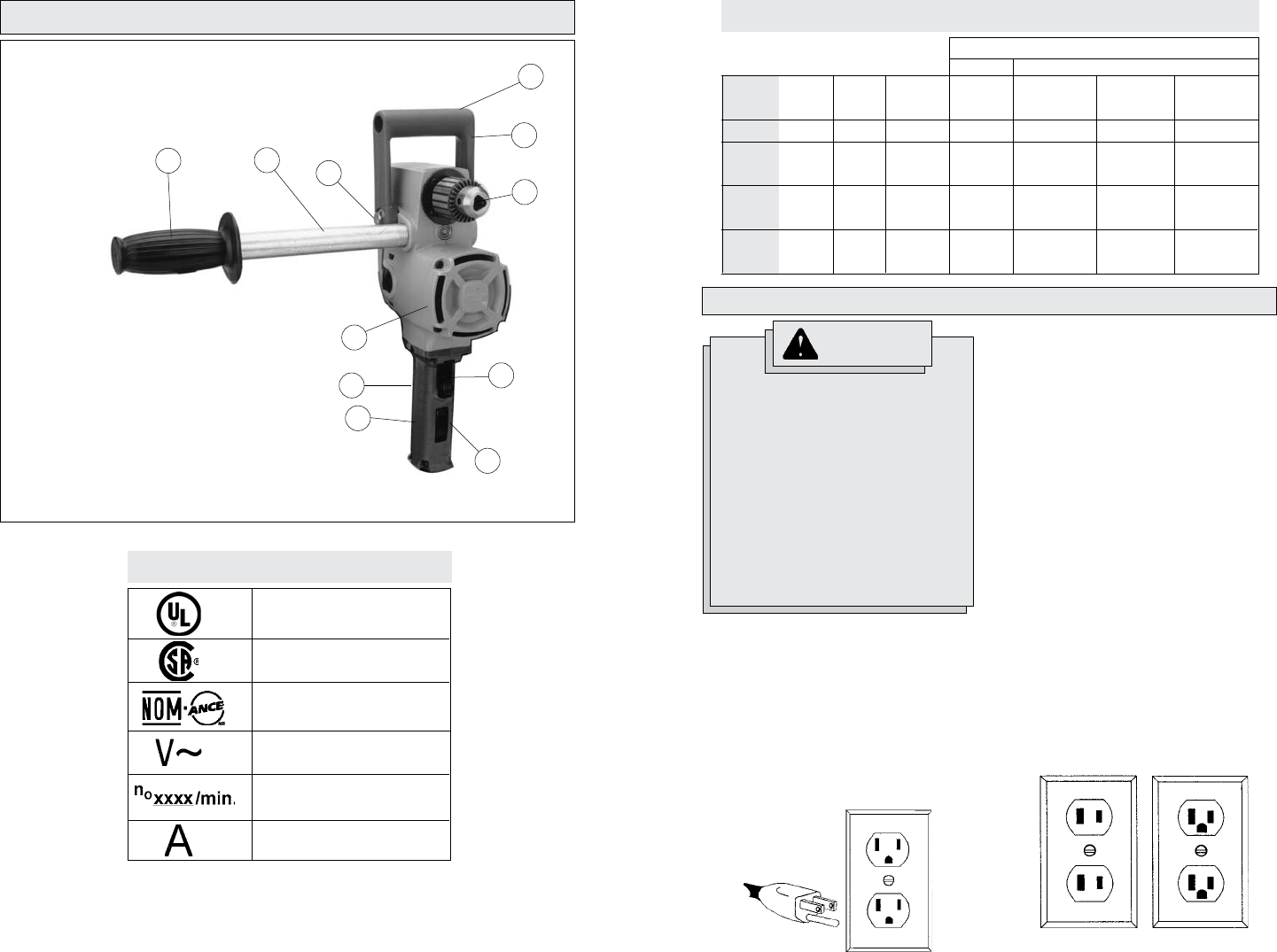
Your tool must be plugged into an appropri-
ate outlet, properly installed and grounded in
accordance with all codes and ordinances.
The plug and outlet should look like those
in Figure A.
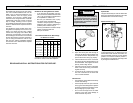
Double Insulated Tools:
Tools with Two Prong Plugs
Tools marked “Double Insulated” do not
require grounding. They have a special
double insulation system which satisfies
OSHA requirements and complies with
the applicable standards of Underwriters
Laboratories, Inc., the Canadian Standard
Association and the National Electrical
Code. Double Insulated tools may be used
in either of the 120 volt outlets shown in
Figures B and C.
Grounded Tools:
Tools with Three Prong Plugs
Tools marked “Grounding Required” have a
three wire cord and three prong grounding
plug. The plug must be connected to a prop-
erly grounded outlet (See Figure A). If the
tool should electrically malfunction or break
down, grounding provides a low resistance
path to carry electricity away from the user,
reducing the risk of electric shock.
Fig. B
Fig. C
Fig. A
Improperly connecting the grounding
wire can result in the risk of electric
shock. Check with a qualified electri-
cian if you are in doubt as to whether
the outlet is properly grounded. Do
not modify the plug provided with
the tool. Never remove the grounding
prong from the plug. Do not use the
tool if the cord or plug is damaged.
If damaged, have it repaired by a
MILWAUKEE service facility before
use. If the plug will not fit the outlet,
have a proper outlet installed by a
qualified electrician.
GROUNDING
WARNING
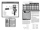
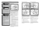
FUNCTIONAL DESCRIPTION
1. Spade Handle
2. Chuck
3. Trigger Switch
4. Reversing Switch
5. Switch Handle
6. Motor Housing
7. Gear Shift Lever
8. Pipe Handle
9. Insulated Gripping Surfaces
6
9
9
8
1
2
3
9
7
5
4
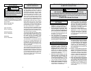
Amperes
Symbology
Canadian Standards
Association
Underwriters
Laboratories, Inc.
Volts Alternating Current
No Load Revolutions
per Minute (RPM)
Mexican Approvals Marking
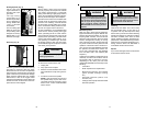
Wood
Capacity
WithShip
Auger Bit
1-1/2"
1-1/4"
1-1/2"
1-1/4"
1-1/2"
1-1/4"
1-1/2"
With
Selfeed Bit
2-9/16"
1-3/8"
4-5/8"
1-3/8"
4-5/8"
1-3/8"
4-5/8"
Volts
AC
120
120
120
120
Speed
-
High
Low
High
Low
High
Low
No Load
RPM
900
1200
300
1200
300
1200
300
With
Twist Bit
7/16"
5/16"
1/2"
5/16"
1/2"
5/16"
1/2"
With Auger
Bit
1-1/2"
1-1/8"
1-1/2"
1-1/8"
1-1/2"
1-1/8"
1-1/2"
Steel
Specifications
Cat. No.
1670-1
1675-1
1675-6
1676-6