


page 6
OPERATION
Using the Transport Lock
The transport lock locks down the handle for transporting and storing
the tool. To release the transport lock, push down the handle and pull out
the transport lock. To lock the transport lock, push down the handle and
push in the transport lock.
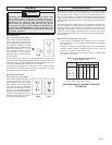
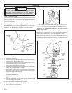
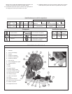
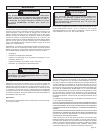
Removing and Installing Blades (Fig. 1)
MILWAUKEE recommends using only MILWAUKEE 14" Dry-Cut blades.
Before operating the tool, make sure the blade is in good condition as
described in the “Specific Safety Instructions - Dry-Cut Machines”.
To change blades:
1. Unplug the tool.
2. Release the transport lock.
3. Loosen the wing nut on the spindle guard door and rotate the door to
expose the blade arbor and blade screw.
4. Press down the spindle lock lever and loosen the blade screw
(counterclockwise) with the wrench provided.
Caution: Keep finger away from sharp teeth.
5. Pull back the lower guard and remove the blade screw, spring washer,
washer, outer flange and blade (if installed).
6. Check the two (2) blade flanges to be sure they are in good condition.
Remove any nicks or burrs, which could cause uneven cutting
pressure and result in blade damage.
Before installing a blade, always inspect it for damage. Replace
damaged blades immediately.
7. Install the blade, outer flange, washer, spring washer and blade screw
(Fig. 1).
8. Press down the spindle lock lever while tightening the blade screw
(clockwise) with wrench provided.
9. Check the blade for free rotation after installation.
10. Allow the lower guard to return to its original position.
11. Return wrench to wrench storage.
To reduce the risk of injury, always unplug tool before
attaching or removing accessories. Use only specifically
recommended accessories. Others may be hazardous.
WARNING!
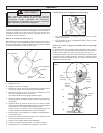
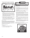
Using the Quick Release Lever (Fig. 2)
1. To release the quick release lever, rotate the lever fully to the left.
2. To lock the quick release lever, rotate the lever fully to the right.
Release
Lock
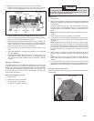
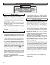
Supporting the Workpiece and Adjusting the Vise and Fence
System (Figs. 3 & 4)
The adjustable vise and fence system holds the workpiece in the
desired position. The vise plate and fence can be moved backward or
forward and can be adjusted to any angle between 90° and 45°.
When adjusting the system, the vise and fence should be positioned so
the centerline of the wheel hub is in line with or behind the centerline of
the workpiece, toward the rear of the tool (Fig. 3). The workpiece should
be resting flush with the base of the machine.
Fig. 2
Fig. 1
Lower guard
Blade
Outer flange
Washer
Blade screw
Spring
washer
Inner flange
Fig. 3
Blade
Center
line of
hub
Vise plate
Workpiece
types
A.
B.
C.
D.
Quick adjust
fence
Preferred
cutting
area