


4
5
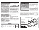
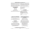
Grounded Tools:
Tools with Three Prong Plugs
Tools marked “Grounding Required” have a three
wire cord and three prong grounding plug. The
plug must be connected to a properly grounded
outlet (See Figure A). If the tool should electrically
malfunction or break down, grounding provides a
low resistance path to carry electricity away from
the user, reducing the risk of electric shock.
The grounding prong in the plug is connected
through the green wire inside the cord to the
grounding system in the tool. The green wire in the
cord must be the only wire connected to the tool's
grounding system and must never be attached to
an electrically “live” terminal.
Your tool must be plugged into an appropriate out-
let, properly installed and grounded in accordance
with all codes and ordinances.
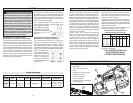
The plug and outlet should
look like those in Figure A.
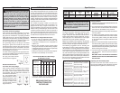
Double Insulated Tools:
Tools with Two Prong Plugs
Tools marked “Double Insulated” do not require
grounding. They have a special double insula-
tion system which satisfi es OSHA requirements
and complies with the applicable standards of
Underwriters Laboratories,
Inc., the Canadian Stan-
dard Association and the
National Electrical Code.
Double Insulated tools may
be used in either of the
120 volt outlets shown in
Figures B and C.
Fig. B
Fig. C
Fig. A
GROUNDING
WARNING Improperly connecting the
grounding wire can result in the risk of elec-
tric shock. Check with a qualifi ed electrician
if you are in doubt as to whether the outlet is
properly grounded. Do not modify the plug
provided with the tool. Never remove the
grounding prong from the plug. Do not use
the tool if the cord or plug is damaged. If
damaged, have it repaired by a MILWAUKEE
service facility before use. If the plug will not
fi t the outlet, have a proper outlet installed by
a qualifi ed electrician.
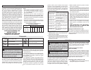
Grounded tools require a three wire extension
cord. Double insulated tools can use either a two
or three wire extension cord. As the distance from
the supply outlet increases, you must use a heavier
gauge extension cord. Using extension cords with
inadequately sized wire causes a serious drop in
voltage, resulting in loss of power and possible tool
damage. Refer to the table shown to determine the
required minimum wire size.
The smaller the gauge number of the wire, the
greater the capacity of the cord. For example, a 14
gauge cord can carry a higher current than a 16
gauge cord. When using more than one extension
cord to make up the total length, be sure each cord
contains at least the minimum wire size required. If
you are using one extension cord for more than one
tool, add the nameplate amperes and use the sum
to determine the required minimum wire size.
Guidelines for Using Extension Cords
• If you are using an extension cord outdoors,
be sure it is marked with the suffi x “W-A” (“W”
in Canada) to indicate that it is acceptable for
outdoor use.
• Be sure your extension cord is properly wired
and in good electrical condition. Always replace
a damaged extension cord or have it repaired by
a qualifi ed person before using it.
• Protect your extension cords from sharp objects,
excessive heat and damp or wet areas.
READ AND SAVE ALL
INSTRUCTIONS FOR
FUTURE USE.
Recommended Minimum Wire Gauge
for Extension Cords*
Extension Cord Length
* Based on limiting the line voltage drop to
fi ve volts at 150% of the rated amperes.
Nameplate
Amperes
0 - 2.0
2.1 - 3.4
3.5 - 5.0
5.1 - 7.0
7.1 - 12.0
12.1 - 16.0
16.1 - 20.0
25'
18
18
18
18
16
14
12
75'
18
18
16
14
12
10
100'
18
16
14
12
10
150'
16
14
12
12
50'
18
18
18
16
14
12
10
EXTENSION CORDS
ASSEMBLY
WARNING To reduce the risk of injury,
always unplug tool before attaching or remov-
ing accessories or making adjustments. Use
only specifi cally recommended accessories.
Others may be hazardous.
Specifi cations
Tool Capacities
Cat. No. Volts Amps FPM
Recommended
Blades
Round
Stock
Rectangular
Stock
6230N
6236N
120 AC
120 AC/DC
10.5
Lo 5.5 / Hi 10.5
0-420
320 / 420
Bi-Metal
Bi-Metal
4-3/4”
4-3/4”
4-3/4” x 4-3/4”
4-3/4” x 4-3/4”
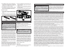
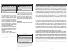
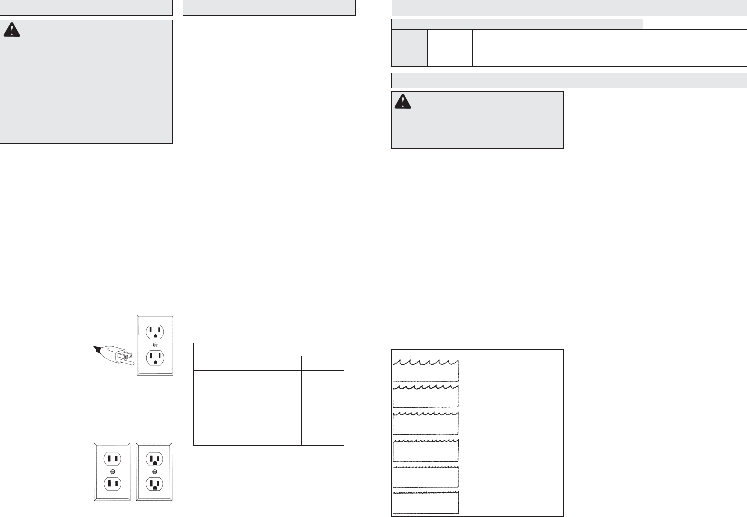
Blades and Blade Selection
The blade dimensions required for the band saws
are: .020" thickness, 1/2" width and 44-7/8" in
length. The special .020" thickness reduces fl exure
fatigue and provides maximum tooth life. To maxi-
mize cutting life, use a blade with the correct pitch
(teeth per inch) for the specifi c cutting job.
Blades are available in several pitches. To select the
proper blade, three factors should be considered:
The size, shape, and type of material to be cut.
The following suggestions are for selecting the
right blade for various cutting operations. Keep in
mind that these are broad guidelines and that blade
requirements may vary depending upon the specifi c
size, shape and type of material to be cut. Gener-
ally, soft materials require coarse pitch blades and
hard materials require fi ne pitch blades. Use coarse
pitch blades for thick work and fi ne pitch blades for
thin work. It is important to keep at least three teeth
in the cut (see "Typical Application").
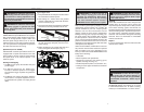
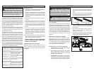
Changing Blades
1. UNPLUG THE TOOL BEFORE REMOVING OR
INSTALLING BLADES.
2. Turn the tension lock handle located on the front
of the saw 180° counterclockwise. This releases
the tension on the blade for easy removal.
3. Remove the blades from the pulley fi rst and then
from the guides.
4. To install a new blade, with the pulleys facing
up, insert the blade between the rollers and the
faces of the guides, making sure that the teeth
on the left side of the tool point towards the rear
of the tool.
5. With one hand, hold the blade in place between
the rollers and the guides and use the other hand
to position the blade around the pulleys. Be sure
that the blade lies freely within the guard channel
before starting the tool motor.
6. Turn the tension lock handle 180° clockwise to
lock the position. This will secure the blade on
the pulleys.
BE SURE THAT THE BLADE IS PROPERLY
SEATED ON THE PULLEYS BEFORE START-
ING THE CUT.
Adjusting the Work Steady Rest
To raise or lower the rest, loosen, but do not re-
move, the two adjusting screws. Slide the rest to the
desired position. Tighten the screws securely.
• For tough stock 1/2" to 3-3/8" in
diameter or width (available in
carbon steel only).
• For tough stock 3/8" to 1" in
diameter or width (available in
carbon steel only).
• For tough stock 3/16" up to
4-3/4" in diameter or width.
• For tough stock 5/32" to 3/4" in
diameter or width.
• For thin-wall tubing and thin
sheets heavier than 21 gauge.
• For thin-wall tubing and thin
sheets heavier than 21 gauge.
Fig. 1
6 Teeth per Inch
8 Teeth per Inch
10 Teeth per Inch
14 Teeth per Inch
18 Teeth per Inch
24 Teeth per Inch