


page 5
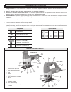
TOOL ASSEMBLY
To reduce the risk of injury, always unplug
tool before attaching or removing accessories
or making adjustments. Use only specifically
recommended accessories. Others may be
hazardous.
WARNING!
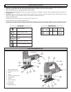
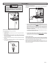
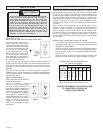
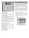
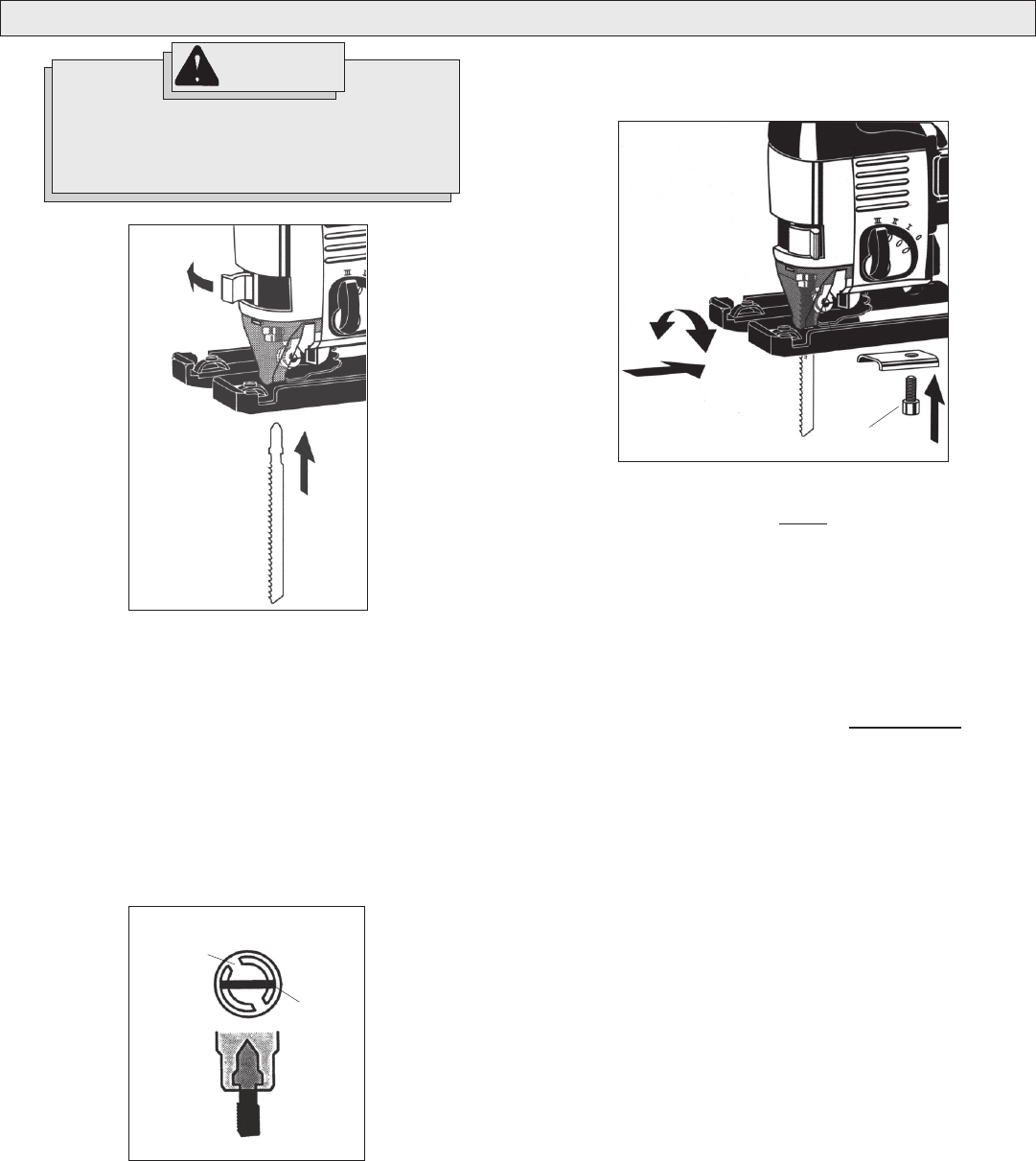
Installing saw blades
This tool uses only T-Shank jig saw blades.
1. Unplug the tool.
2. Push the Quik-Lok tension lever as far as it will go and hold it in
position (Fig. 1).
3. Fit the saw blade into the groove in the support roller and push it
firmly into the plunger as far as it will go; the lug of the saw blade
must be in the plunger.
4. Release the Quik-Lok tension lever and the saw blade is automati-
cally held.
5. Check that the saw blade is held firmly; the slot in the plunger will be
at an angle to the saw (Fig. 2).
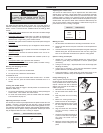
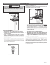
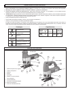
Adjusting the shoe (Fig. 3)
The shoe may be tilted up to 45° in either direction and moved forward or
backward.
1. To set a tilt angle for angle cuts and bevels, loosen the shoe
screw, pull the base backward
slightly until the retaining lugs are no
longer engaged. Tilt to the required preset angle (15°, 30°, or 45°) as
read on the tilt angle scale. Push back into the retaining lugs and
tighten the shoe screw. If angles other than the presets are re-
quired, set the desired angle and tighten the shoe screw without
engaging the retaining lugs.
If very exact angles are needed it is recommended that a test cut
and subsequent adjustment be made.
2. To move the shoe back for plunge cuts or cuts in corners,
loosen the shoe screw and pull the shoe
all the way back. The shoe
screw will fit into a slot to hold the shoe at 0°.
Using the Shoe Cover
The non-marring shoe cover is used to prevent marring and scratching
of the workpiece surface. To attach the shoe cover, hook the front of the
cover over the steel shoe. Next, snap the rear of the shoe cover to the
steel shoe. Be sure both sides are snapped in place.
When the shoe cover is not needed, remove it by pulling the tabs on rear
of the shoe cover outward from the steel shoe. Unhook the front of the
shoe cover and remove.
Slot
Blade
Fig. 2
Fig. 1
Fig. 3
Shoe screw