


4
5
• Hold power tool by insulated gripping surfaces,
when performing an operation where the cutting
accessory may contact hidden wiring or its own
cord. Cutting accessory contacting a live wire may
make exposed metal parts of the power tool live and
could give the operator an electric shock.
• Use clamps or another practical way to secure
and support the workpiece to a stable platform.
Holding the work by hand or against your body
leaves it unstable and may lead to loss of control.
• Keep hands away from all cutting edges and
moving parts.
• Maintain labels and nameplates. These carry
important information. If unreadable or missing,
contact a MILWAUKEE service facility for a free
replacement.
• WARNING Some dust created by power sanding,
sawing, grinding, drilling, and other construction
activities contains chemicals known to cause
cancer, birth defects or other reproductive harm.
Some examples of these chemicals are:
• lead from lead-based paint
• crystalline silica from bricks and cement and other
masonry products, and
•arsenic and chromium from chemically-treated
lumber.
Your risk from these exposures varies, depending
on how often you do this type of work. To reduce
your exposure to these chemicals: work in a well
ventilated area, and work with approved safety
equipment, such as those dust masks that are spe-
cially designed to fi lter out microscopic particles.
SPECIFIC SAFETY RULES
FUNCTIONAL DESCRIPTION
Double Insulated
Volts Alternating Current
Amps
No Load Strokes per Minute
(SPM)
Mexican Approvals Marking
SYMBOLOGY
Cat.
No.
Volts
AC
Amps
No Load
Strokes Per
Minute
Length
of
Stroke
6278-20 120V~50-60Hz 6 500-3000 1"
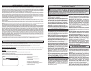
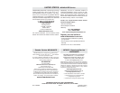
SPECIFICATIONS
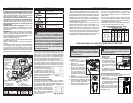
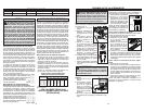
1.Quik-Lok
tension lever
2.Transparent
blade cover
3. Anti-Splinter
Device
4. Blade
5. Shoe cover
6. Shoe
7. Orbital action
selector lever
7
6
5
9
11
10
8
12
13
8. Shoe adjustment
lever
9. Tilt angle scale
10. Dust collection
attachment
11. Trigger
12. Lock button
13. Speed selector dial
Fig. B
Fig. C
Fig. A
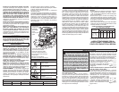
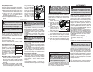
GROUNDING
WARNING Improperly connecting the
grounding wire can result in the risk of
electric shock. Check with a qualifi ed electri-
cian if you are in doubt as to whether the
outlet is properly grounded. Do not modify
the plug provided with the tool. Never remove
the grounding prong from the plug. Do not
use the tool if the cord or plug is damaged. If
damaged, have it repaired by a MILWAUKEE
service facility before use. If the plug will not
fi t the outlet, have a proper outlet installed by
a qualifi ed electrician.
Grounded Tools: Tools with Three Prong Plugs
Tools marked “Grounding Required” have a three
wire cord and three prong grounding plug. The
plug must be connected to a properly grounded
outlet (See Figure A). If the tool should electrically
malfunction or break down, grounding provides a
low resistance path to carry electricity away from
the user, reducing the risk of electric shock.
The grounding prong in the plug is connected
through the green wire inside the cord to the
grounding system in the tool. The green wire in the
cord must be the only wire connected to the tool's
grounding system and must never be attached to
an electrically “live” terminal.
Your tool must be plugged into
an appropriate outlet, properly
installed and grounded in ac-
cordance with all codes and ordi-
nances. The plug and outlet should
look like those in Figure A.
Double Insulated Tools:
Tools with Two Prong Plugs
Tools marked “Double Insulated” do not require
grounding. They have a special double insula-
tion system which satisfi es OSHA requirements
and complies with the applicable standards of
Underwriters Laboratories, Inc.,
the Canadian Standard Asso-
ciation and the National Elec-
trical Code. Double Insulated
tools may be used in either of
the 120 volt outlets shown in
Figures B and C.
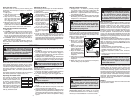
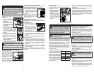
Using the Transparent
Blade Cover
1. Unplug tool.
2. To install, place the
transparent blade cov-
er in front of the blade
and slide it into place.
The tabs will snap into
the slots on the hous-
ing.
3. To remove, press in
the sides of the transparent blade cover and pull
away from the blade.
Using the Anti-Splinter Device
The anti-splinter device helps stabilize the work-
piece and reduce workpiece splinter.
1. Unplug tool.
2. Slide the anti-splinter de-
vice onto the shoe. Make
sure the anti-splinter device
is installed fl ush with the
bottom of the shoe.
NOTE: Do not use the anti-
splinter device or dust collec-
tion attachment when making
bevel/angle cuts.
Grounded tools require a three wire extension
cord. Double insulated tools can use either a two
or three wire extension cord. As the distance from
the supply outlet increases, you must use a heavier
gauge extension cord. Using extension cords with
inadequately sized wire causes a serious drop in
voltage, resulting in loss of power and possible tool
damage. Refer to the table shown to determine the
required minimum wire size.
The smaller the gauge number of the wire, the
greater the capacity of the cord. For example, a 14
gauge cord can carry a higher current than a 16
gauge cord. When using more than one extension
cord to make up the total length, be sure each cord
contains at least the minimum wire size required. If
you are using one extension cord for more than one
tool, add the nameplate amperes and use the sum
to determine the required minimum wire size.
READ AND SAVE ALL INSTRUCTIONS FOR FUTURE USE.
Recommended Minimum Wire Gauge
for Extension Cords*
Extension Cord Length
* Based on limiting the line voltage drop to fi ve volts
at 150% of the rated amperes.
Nameplate
Amperes
0 - 2.0
2.1 - 3.4
3.5 - 5.0
5.1 - 7.0
7.1 - 12.0
12.1 - 16.0
16.1 - 20.0
25'
18
18
18
18
16
14
12
75'
18
18
16
14
12
10
100'
18
16
14
12
10
150'
16
14
12
12
50'
18
18
18
16
14
12
10
EXTENSION CORDS
ASSEMBLY
WARNING To reduce the risk of injury,
always unplug tool before changing or
removing accessories. Only use accessories
specifi cally recommended for this tool. Others
may be hazardous.
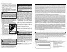
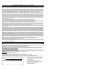
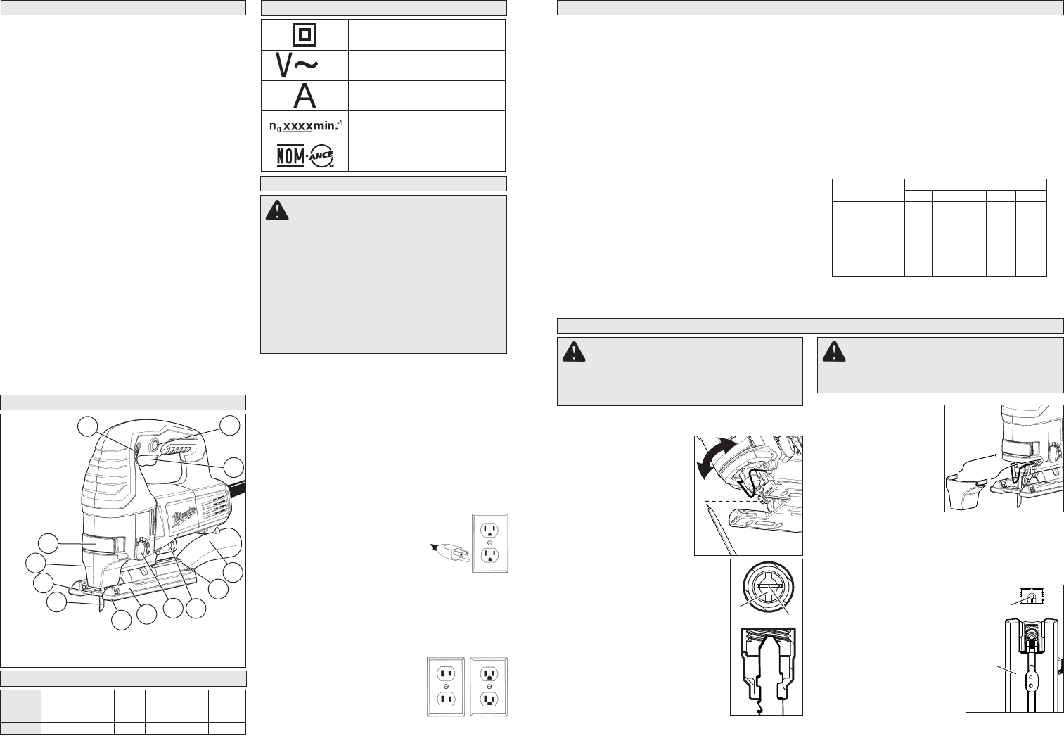
Installing Saw Blades
Use only T-Shank jig saw blades.
1. Unplug tool.
2. Remove anti-splinter
device and transparent
blade cover.
3. Pull out and hold the
Quik-Lok tension lever.
4. Fit the saw blade into
the groove in the support
roller and push it fi rmly
into the plunger as far
as it will go; the lug of the
saw blade must be in the
plunger.
5. Release the Quik-Lok tension
lever to secure the saw blade.
6. Check that the saw blade is held
fi rmly; the slot in the plunger will
be at an angle to the blade.
7. Install the anti-splinter device
and transparent blade cover.
Slot
Blade
Anti-splinter
device
Shoe
Guidelines for Using Extension Cords
• If you are using an extension cord outdoors,
be sure it is marked with the suffi x “W-A” (“W”
in Canada) to indicate that it is acceptable for
outdoor use.
• Be sure your extension cord is properly wired
and in good electrical condition. Always replace
a damaged extension cord or have it repaired by
a qualifi ed person before using it.
• Protect your extension cords from sharp objects,
excessive heat and damp or wet areas.
WARNING To reduce the risk of injury,
always use saw with transparent blade
cover in place. Sawdust and wood chips can
be thrown during use.
4
2
1
3