


Disassembly:
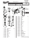
1, 2, 3, 4, 8 Remove bolt (1) from top cap (8) using a 4 mm hex key and remove assembly (2, 3, 4)
5, 8 Remove four screws (5) from top cap (8) using a 4 mm hex key.
8, 9, 10, 11, 12,
13, 14
Using a 1/8 in. punch, gently push valve assembly (9, 10, 11, 12, 13, and 14) out of top cap (8) through the holes in the cover.
16, 17, 18, 19, 20,
21, 22, 23, 24,
25, 45
Remove press ring (16) from top of cylinder (20), turn tool body (45) over and tap outside edge of tool body against a piece of
wood to separate assembly (17-25) from tool body.
20, 22, 23, 24 Remove cylinder ring (24) from cylinder (20) prior to removing cylinder spacer assembly (22, 23).
45,50,79, 106,112 Remove screw (106) and washer (79) from tool body (45) to lift magazine coil assembly (112) o nose piece (50).
37, 38, 39, 40, 41,
42, 43, 44, 45, 111
Remove trigger valve assembly (111) from tool body (45) by placing a 3/32 in. (2.5mm) punch inside half-moon slot of retainer
(41) and gently tapping shaft of selector (42). Remove spring (43), retainer (41), and ring (44). Remove trigger and spring (39,40)
from tool body and push pins (37, 38) out of tool body (45) just far enough to remove valve assembly. Note: Once pins (37, 38)
have been moved, trigger valve assembly (111) can be gently pushed out of the tool body from the inside handle area of the
tool body using a at blade screwdriver.
Note: Use service xture #61-60-0005 to move spring pins (42, 43), or use a 1/8" punch.
Reassembly:
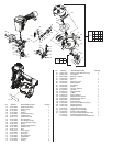
50, 63, 64 Apply Blue Loctite
®
, 242, onto threads of screws (64) prior to installing feed piston cap (63) onto nose assembly (50).
50, 78, 80 Apply Blue Loctite
®
onto threads of screw (80) prior to installing work contact element cover (78) onto nose assembly (50).
90, 92, 93 Apply Red Loctite
®
onto threads of screws (93) when securing contact element bracket (90) to contact element bracket A
(92).
37, 38, 45, 111 Reinstall trigger valve assembly (111) into tool body (45) by aligning the grooves in the valve assembly with the two holes for
spring pins (37, 38). Drive spring pins into tool body until they are ush with the casting surface.
Use service xture #61-60-0005 to reinstall pins (37, 38).
39, 40, 41, 42, 43,
44, 45
Reinstall selection lever assembly (41, 42, 43, 44,) and trigger assembly (39, 40) by doing the following.
• Place spring (43) onto shaft of selection lever (42)
• Position spring (40) and trigger (39) over plunger of trigger valve assembly (111)
• Insert selection lever assembly (42, 43) into tool body (45) and align half-moon slot of retainer (41) with half-moon
shaft of selection lever (42) and snap retainer assembly (41, 44) onto the shaft
20, 21, 22, 23 Install o-ring (21) onto cylinder (20) prior to installing cylinder spacer assembly (22, 23).
20, 22, 23, 24 Install cylinder ring (24) onto cylinder (20) only after cylinder ring assembly (22, 23) have been installed.
Note: Large anged end of cylinder ring (24) must facing the top of cylinder (20) when installed.
17, 18, 19, 20, 21,
22, 23, 24, 25,
45, 50
Install preassembled driver assembly (17, 18, and 19) into preassembled cylinder assembly (20, 21, 22, 23, 24, and 25) and
install assembled components into tool body (45). Note: Orientation of driver assembly (19) must match orientation in nose
assembly (50).
8, 16, 20 Install press ring (16) onto top of cylinder (20) with wide edge facing toward top cap (8).
2, 6, 7 Install bumper band pad (7) into bumper band (6) with the word ‘TOP’ facing toward deector (2).
47, 48 Install smooth side of lter (47) toward end cap (48).
1, 8 Apply Blue Loctite
®
onto threads of screw (1) if removed from top cap (8).
PAGE 2 OF 2
BULLETIN NO. 54-43-0030 Mar. 2006