


- 6 -
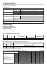
2. Power line
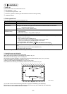
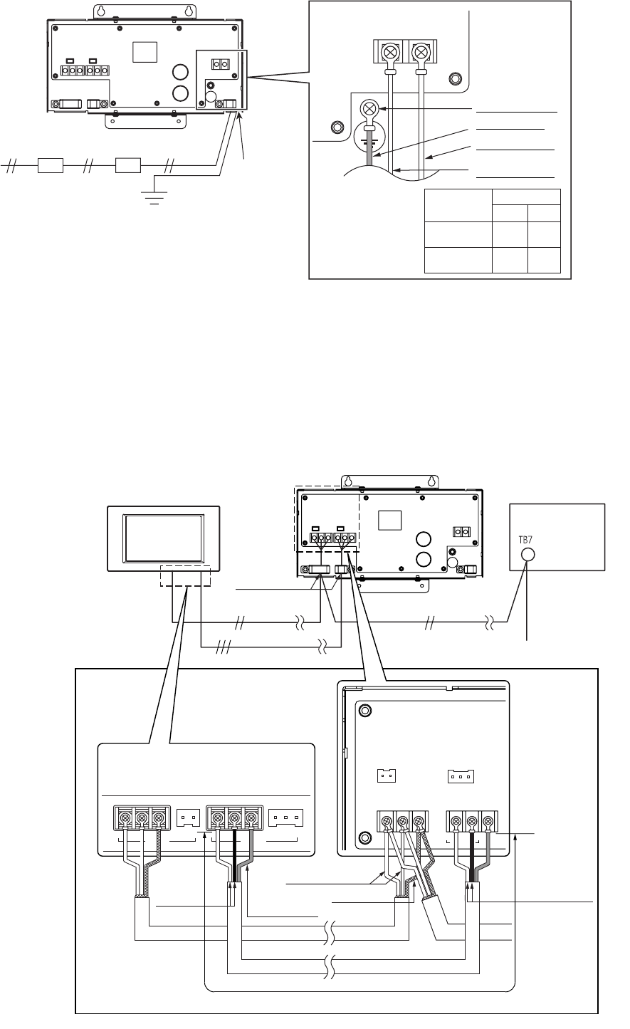
Wire the power and ground cables to L/L1, N/L2 and the ground cable terminals on TB1 as shown in Fig. 4-2.
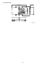
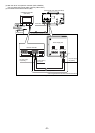
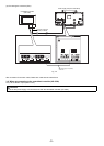
3. DC Power Supply and M-NET Transmission Line
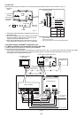
3-1. When connecting to the centralized controller (AG-150A)
(1) Without the use of an expansion controller (PAC-YG50ECA)
(a) Connected via the terminal block
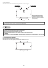
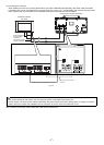
The DC power cable and M-NET transmission line connect as shown in Fig. 4-3. The DC power cable has a 24VDC and a GND
polarity. Connect it to the terminals in accordance with the polarity. Connect the M-NET transmission line to the A, B
(non-polarity), and S (shield) terminal block.
TB1
L/L1 N/L2
Applicable area
EU
US
L
L1
N
L2
Power cable
Ԙԙ
㨪100-240V
A Breaker for
wiring
B
Ground-fault
interrupter
Power source
100-240VAC
50Hz/60Hz
BAPower cable
Ground
Ground cable
Attach the
power line
Power line terminal
Ground cable
Power cable 2
* Use L/N in EU.
* Use L1/L2 in the U.S.
* Use a ring terminal to connect to the terminal block.
Fig. 4-2
Ground terminal
Power cable 1
*1 Install ground-fault interrupter and breaker for wiring on
the power supply.
*2 Do not use anything other than a breaker and fuse with
the correct capacity. Using a fuse or wire of too large
capacity may cause malfunction or fire.
*3
Note : When installing the unit, use the switch having a
contact separation of at least 3mm (
1
/
8
in.) in each pole.
FG
V+
V-A B S CN1 CN2
24VDCM-NET
ABS V+V-FG
M-NET Output
CN1 CN2
TB2 TB3
24VDC
Power supply unit (PAC-SC51KUA)
Centralized controller
(AG-150A)
Outdoor unit
Cable Clamp
M-NET transmission line
(Centralized control line)
DC power supply line (24VDC) *Polarized
* Use a ring terminal to connect to the terminal block
Back of controller
Shield
M-NET transmission
A, B line (Non-Polarity)
50 m (164 ft) or less
Fig. 4-3
Function earthing
(ground) line
DC power
supply
line (Polarity)
Power supply unit
DC power supply
line (Polarity)
00gb_WT05372X04_7.book Page 6 Monday, September 28, 2009 2:03 PM