HVAC Advanced Products Division
Mitsubishi Electric & Electronics USA, Inc.
3400 Lawrenceville Suwanee Rd.
Suwanee, GA 30024
Tele: 678-376-2900 • Fax: 800-889-9904
Toll Free: 800-433-4822 (#4)
www.mehvac.com
Specications are subject to change without notice.
C SD - PURY-P192TSHMU-A-BS - 1 - 200809 © MITSUBISHI ELECTRIC / HVAC 2008
Certificate Number FM33568
Certificate Number EC97J1227
Mitsubishi Electric Air Conditioning & Refrigeration Systems Works acquired ISO
9001 certification under Series 9000 of the International Standard Organization (ISO)
based on a review of quality warranties for the production of refrigeration and air
conditioning equipment.
ISO Authorization System
The ISO 9000 series is a plant authorization system relating to quality warranties as
stipulated by the ISO. ISO 9001 certifies quality warranties based on the "design,
development, production, installation and auxiliary services" for products built at
an authorized plant.
Mitsubishi Electric Air Conditioning & Refrigeration Systems Works acquired environmental
management system standard ISO 14001 certification.
The ISO 14000 series is a set of standards applying to environmental protection set by the
International Standard Organization (ISO).
(Mounting pitch)
ø45 Knockout hole
(Use when twinning kit (optional
parts) is mounted.)
Front access hole
ø34 Knockout hole
NO.
For pipes
For transmission cables
Usage
Bottom access hole
Front access hole
Front access hole
Bottom access hole
Front access hole
140 X 77 Knockout hole
150 X 94 Knockout hole
ø65 Knockout hole
Front access hole
For wires
ø62.7 or ø34.5 Knockout hole
ø43.7 or ø22.2 Knockout hole
Specifications
(10-11/16)
(3-5/32) (3-5/32)
(41-3/4)
2 X 2-14(9/16)
X 20(13/16) Oval hole
(23/32)(23/32)
724 (721 ~ 727)
(29-15/16)
(28-13/32 ~ 28-5/8)
(28-17/32)
(3-23/32)
(5-23/32)
(3-5/16)
(3-9/32)
(5-29/32)
(10-3/8)
(64-31/32)
(55-17/32)
(9-15/32)
(48-1/16)
(29-15/16)
(5-3/16)
(5-23/32)
(11-7/8)
(8-17/32)
(8-9/16)
(5-3/4)
(3-9/16)
(3-1/16)
(2-5/16)
(5-17/32)
(2-31/32)
(10-11/16)
(9-29/32)
(9-9/32)
(29-15/16)
(2-3/16)(1)
(1)(2-3/16)
(2-5/32)
ø28.58 Brazed
760
150
8494
271 140
(Mounting pitch)
235
146
2
4
5
7
1
Accessories
Connecting pipe
Low pressure · Pipe (IDø25.4 [1] X IDø22.2 [7/8])················P96 1 pc.
· Pipe (IDø25.4 [1] X IDø28.58 [1-1/8])···········P120 1 pc.
High pressure · Pipe (IDø25.4 [1] X ODø19.05 [3/4])·············P96, P120 1 pc.
·
Elbow (IDø19.05 [3/4] X ODø19.05 [3/4])········P96, P120 1 pc.
55
PURY-P120THMU
(-BS)
*1. Use only the supplied connecting pipes (for bottom
and front piping).
*1
3
6
Refrigerant service
valve <High pressure>
217
7790
58
75
251
55
Refrigerant service
valve <Low pressure>
Refrigerant service
valve <High pressure>
Refrigerant service
valve <Low pressure>
ø22.2 Brazed
Low
pressure
Connection specifications for
the refrigerant service valve
High
pressure
ø19.05 Brazed
PURY-P96THMU
(-BS)
Model
Connecting pipe specifications
1220
760
1650
240
1410
271
216
18
8080
1060
18
301
83
Intake
air
Control box
Intake
air
Service
panel
131
(760)
Discharge air
Intake
air
54
2525
145
263
145
(7/8)
(5-17/32)(3-1/16)
(1-25/32)
(3-23/32)(5-29/32)
(2-9/16)
(1-11/32)
(2-15/32) (1-3/8)
(1-3/4)
(1-1/8)
(7/8)
(3/4)
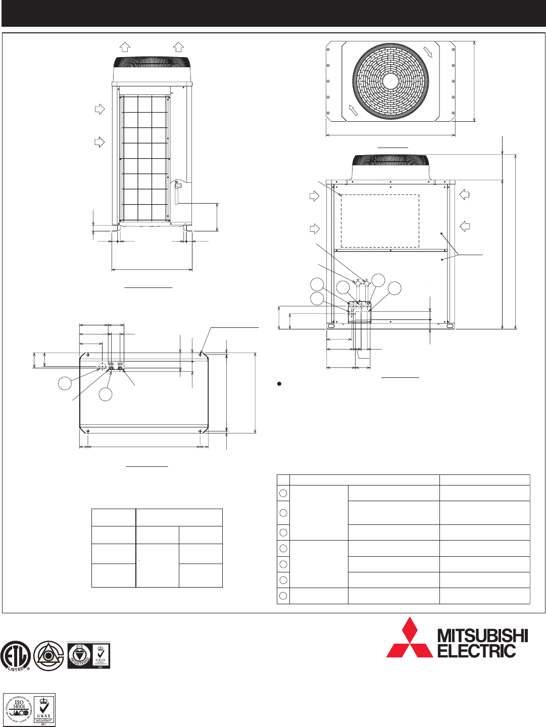
Top view
Left side view
Front view
Bottom view
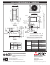
Note 1. Refer to the Engineering or Installation manual for information regarding
necessary clearance around the unit, and installation site requirements.
2. When brazing the pipes, protect the refrigerant service valve by wrapping
it with a wet cloth to keep its temperature under 120°C (248°F).
1
2
4
3
5
6
7
Unit : mm(in)
Modules 1 and 2: PURY-P96THMU-A-BS – DIMENSIONS


