


Installation
4
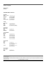
MODEL
SERIAL
xxxxxx
LOT yywwxxx
CHRISTCHURCH ( NEW ZEALAND )
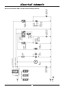
REGULATIONS AND USED ONLY IN A WELL-VENTILATED SPACE. REFER TO THE
THIS APPLIANCE SHALL BE INSTALLED IN ACCORDANCE WITH CURRENT
THIS APPLIANCE MUST BE EARTHED / GROUNDED
MOFFAT LIMITED
INSTRUCTIONS BEFORE INSTALLING AND USING THIS APPLIANCE.
A @ V a.c.
V a.c. Hz kW
CODE
1P+N+E
P8M
USP8M
11.6 115
110-120 50-60 1.45
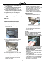
Unpacking
1. Remove all packaging and transit protection including
all protective plastic coating from the exterior stainless
steel panels.
2. Check the proofer / holding cabinet and supplied parts
for damage. Report any damage immediately to the
carrier and distributor.
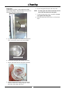
3. Check that the following parts have been supplied with
your proofer / holding cabinet:-
Water Inlet Elbow c/w Rubber Washer.
4. Report any deficiencies to the distributor who supplied
the appliance.
5. Ensure that all the castors are fitted securely.
6. Check that the available electrical supply is correct to as
shown on the Technical Data Plate located on the front
right hand side panel.
- Refer to ‘Specifications’ section, ‘P8M / P12M
Specifications Tables’.
Location
1. Position the proofer / holding cabinet in its working
position.
2. The proofer / holding cabinet should be positioned so
that the control panel and shelves are easily reachable
for loading and unloading.
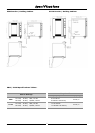
Clearances
To ensure correct ventilation for the motor and controls,
the following minimum installation clearances are to be
adhered to:-
Top 0 mm / 0”.
Rear 0 mm / 0”.
Left-hand side 0 mm / 0”.
Right-hand side 25 mm / 1”.
Electrical Connection
Each proofer / holding cabinet should be connected to an
adequately protected power supply and an isolation switch
mounted adjacent to, but not behind the proofer / holding
cabinet and must be readily accessible to the operator.
This switch must be clearly marked and readily accessible
in case of fire.
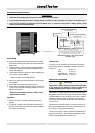
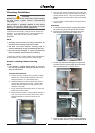
Check that the electricity supply is correct to as shown on
the Technical Data Plate on the front right hand corner of
the proofer / holding cabinet side panel.
The P8 / P12 Proofer / Holding Cabinets are supplied with
electrical cords fitted . Ensure that the appliance is fitted
with the appropriate power cord and plug.
Proofer / Holding Cabinet
Serial Number
Technical Data Plate - Data and Location
(example only)
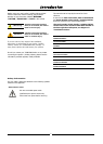
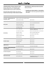
Installation Requirements
*******
Important:
• Installation shall comply with local electrical, health and safety requirements.
• It is most important that this proofer / holding cabinet is installed correctly and that the operation is correct before use.
• If you have any questions regarding the proper installation and / or operation of this proofer / holding cabinet , please
contact your local Turbofan distributor.
This proofer / holding cabinet must be earthed/grounded.
If the supply cord is damaged, it must be replaced by a
suitably qualified person in order to avoid a hazard.
Warning
Current Draw
Electrical Power
Rating
Proofer / Holding Cabinet
Model Number