


PAGE 22 — MQ-WHITEMAN FS2 CONCRETE SAW — PARTS & OPERATION MANUAL — REV. #2 (11/08/01)
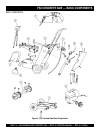
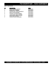
FS2 CONCRETE SAW — INSPECTION -BLADE PLACEMENT
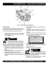
WARNING
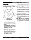
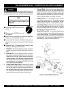
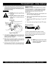
Failure to thoroughly inspect the diamond blade (Figure 9) for
operational safety could result in damage to the blade, the saw,
and may cause injury to the user or others in the operating area.
■
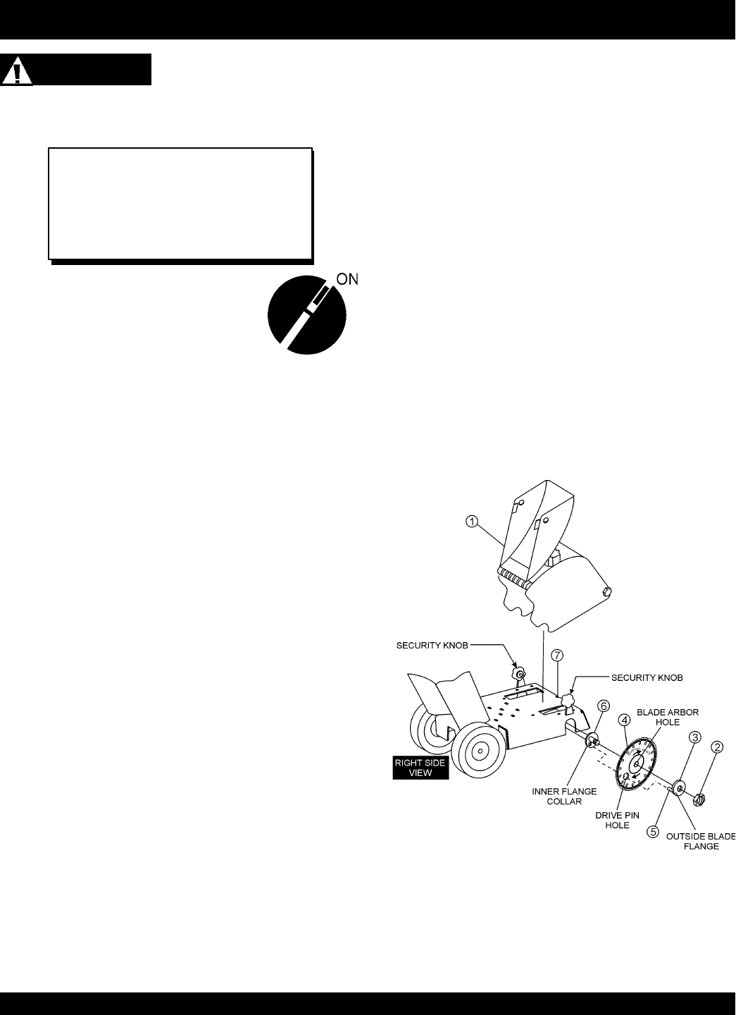
Set the engine ON/OFF switch to the OFF
position.
■
Place the console ON/OFF button in the
OFF position.
■
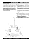
Raise the saw to a high position by cranking the Raise/Lower
handle in a counterclockwise direction.
■
Use the Blade Nut Wrench & Blade Shaft Locking Wrench
stored in the lower section of the console to install the diamond
blade.
■
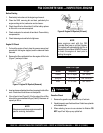
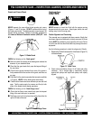
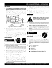
Reference Figure 10 (Diamond Blade Placement) when
removing or installing the diamond blade.
1. Belt Guard – Unscrew the guard security knob and remove
the blade guard from its bayonet fitting and set it beside the
saw.
2. Blade Hex Nut – Unscrew the [blade shaft nut “right hand”
side loosens clockwise, and tightens counter clockwise],
[blade shaft nut “left side” loosens counter clockwise and
tightens clockwise]. Utilize the blade nut wrench and shaft
lock wrench located on the lower inside console cavity. Do
not overtighten the nut (approximately 45-50 ft.-lb/ 61-68
N/m) when finalizing the assembly.
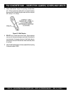
3. Outside Blade Flange (Collar) – Ensure that the outside
blade flange is placed flush against the diamond blade,
and that the flange drive pin goes through the blade pin
hole and seats properly into the inner flange drive pin hole.
The inside surface of the flange must be free of debris and
permit a tight closure on the surface of the blade core.
NOTE
The following steps should be accomplished
before placing the diamond blade on the
blade shaft.
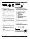
4. Diamond Blade – Ensure that the proper diamond blade
has been selected for the job. Pay close attention to the
directional arrows on the blade, clockwise for right-hand
cutting and counter-clockwise for left-hand cutting, then
place the blade onto the blade shaft, and ensure the arbor
hole of the blade matches the diameter of the shaft.
5. Blade Drive Pin – Line up the blade drive pin with the
inner flange (collar) pin hole. The blade’s operating
directional arrows must point in a “down-cutting” direction
(whether cutting on right side or left) to perform correctly.
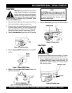
6. Inner Flange (Collar) – This flange is fixed upon the blade
shaft, and is manufactured with a drive pin hole. The inside
surface of the flange must be free of debris and permit a
tight closure on the surface of the blade.
7. Blade Shaft Torque Hole – A conveniently placed opening
on the frame permits the use of the shaft lock wrench to
assist in blade changes. The pointed end of the locking
wrench fits into the saw frame hole and a machined hole in
the blade shaft. Once in place, the blade shaft can not
rotate making it easier to remove the blade nut.
Figure 10. Diamond Blade Placement