


PAGE 28 — MQ-MIKASA MDR-9GH VIBRATORY ROLLER — OPERATION AND PARTS MANUAL — REV. #0 (12/17/03)
MDR-9GH — MAINTENANCE
HDRAULIC AIR EXTRACTION
1. After filling hydraulic oil tank with oil, loosen the oil hose
joint and check that oil is enough to reach the oil suction
and outlet ports in the hydraulic transmission. Tighten the
hose joint securely after checking.
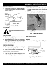
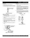
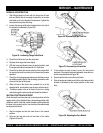
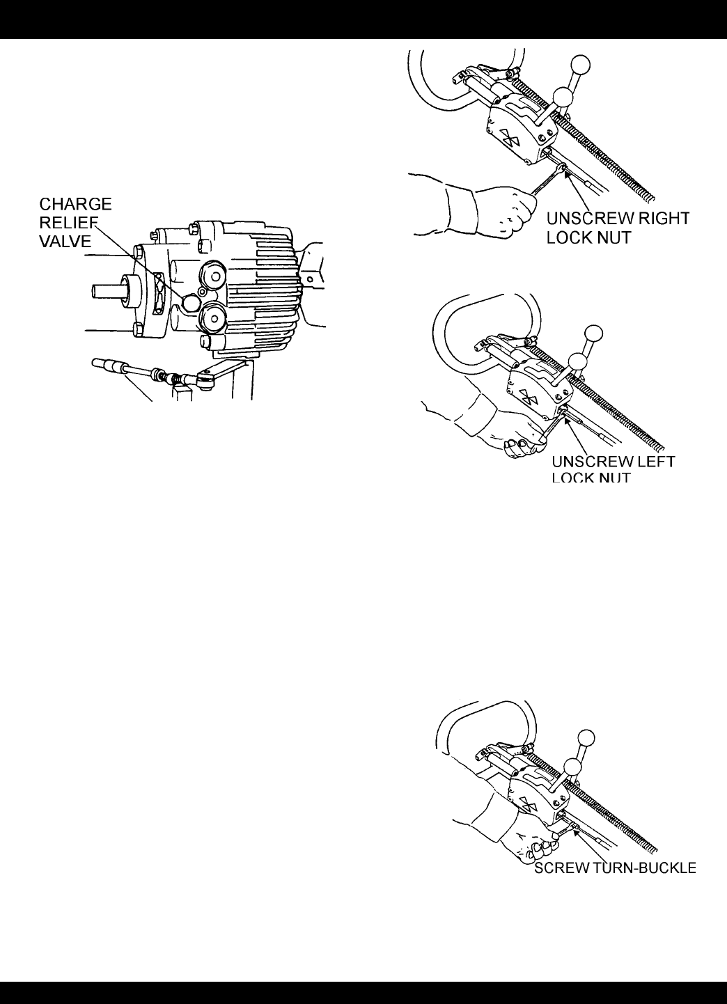
2. Loosen the charge relief valve located on the front side of
the hydraulic transmission (Figure 35).
3. Check that oil flows out from the valve hole.
4. Replace the charge relief valve tightly.
5. With the travel and vibrator levers in neutral position, start
the engine and idle at low speed for 3 to 5 minutes.
6. Check the forward and reverse rotation of the output shaft
by moving the travel lever slowly to its forward and reverse
positions.
7. Check the oil level gauge and make sure that there are no
air bubbles mixed in the oil. After checking, operate the roller
slowly at first then at full speed.
8. When oil level in the tank is low, replenish oil up to the
specified level, and screw the cap securely with a wrench.
9. If bubbles remain in the oil or foam is found, air is being
sucked through the suction side and should be checked.
NEUTRAL POSITION ADJUSTMENT
Once the travel lever has veen set to neutral position with the
engine running, the hydraulic brake is is operating and the roller
should not move. If the roller inches forward or backwards with
the lever in the neutral position, turn-buckle of the cable should
be adjusted as follows:
1. Stop the engine and set the travel lever in the neutral
position.
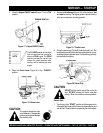
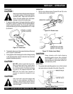
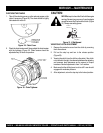
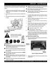
2. Unscrew the two lock nuts on the sides of the cable
(Figures 36 and 37).
Figure 35. Loosening Charge Relief Valve
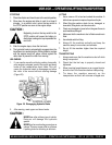
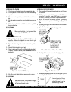
3. If the machine moves forward, screw the turn-buckle
clockwise. If the machine moves backwards, screw the turn-
buckle counterclockwise (Figure 38).
4. Screw back the lock nuts on the turn-buckle.
5. Start the engine and make sure that the roller does not inch
forward or backward at the neutral position of the travel
lever.
Figure 36. Unscrewing Right Lock Nut
Figure 37. Unscrewing Left Lock Nut
Figure 38. Adjusting the Turn-Buckle