


PAGE 24 — MP1 — OPERATION AND PARTS MANUAL — REV. #3 (03/29/10)
Assembly (Gasoline Powered Saws Only)
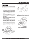
1. Remove the MP1 saw from its container and place it on a
suitable table or platform. Make sure the table or platform can
support the weight of the saw. The saw platform should be
rigid and stationary so that it will not move, sag, or sway due to
the vibrations and movements of the saw.
2. If using the MP1 series
support stand kit
(P/N TRAK14SS),
attach stand to the under-side of the water tray. Follow the
instructions supplied with the support stand kit when attaching
it to the water tray.
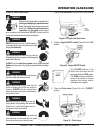
3. The
gasoline powered
saw uses a
mechanical water
pump.
This pump operates by drawing power from the drive V-belts,
and has been adjusted and locked for wet cutting operation
when shipped from the factory.
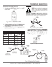
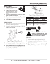
4. Fill the water tray with clean fresh water. The
water
pump
intake (strainer) must always be fully covered by water
to operate effectively
. Also, keep the pump intake free of
sludge, debris and other materials that may accumulate in
the tray.
5. Make certain that the water hose will not come in contact
with the blade or interfere with any moving parts. The best
location for the water pump/strainer is between the splash
shield and the rear of the water tray. This will prevent some
of the abrasive particles from flowing through the pump.
Whenever cleaning, adjusting or lubricating any part of the saw,
MAKE CERTAIN to stop the engine and disconnect the spark
plug wire from the spark plug.
PRE-SETUP
WARNING
PRE-SETUP (GASOLINE)
CAUTIONCAUTION
CAUTIONCAUTION
CAUTION
ALWAYS
position the
strainer
in the water
tray in a manner that will allow the free
movement of the conveyor cart, and clearance
from the cutting blade and cutting action.
The MP1 gasoline model utilizes some of the same procedures
that are used for the MP1 electric models. Please reference pages
20 and 21 for the below referenced procedures:
■
Conveyor Cart Placement
■
Blade Selection and Inspection
■
Saw Blades
■
Blade Installation
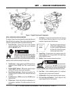
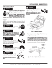
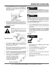
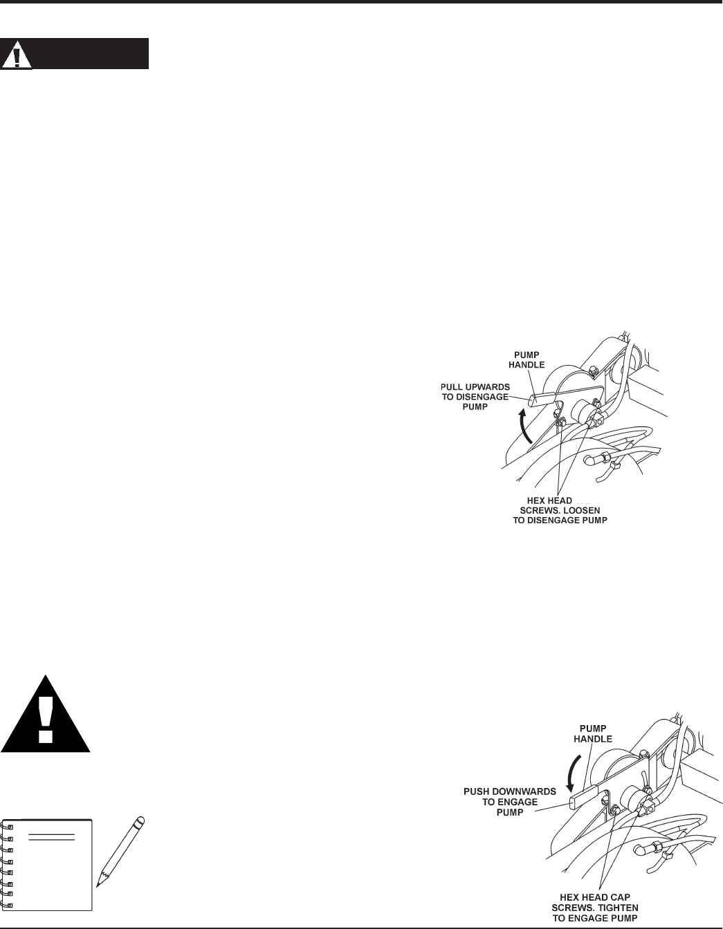
DRY CUTTING (GASOLINE ONLY)
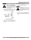
To disconnect the
mechanical water pump
from the drive V-
belts perform the following:
1. Loosen the 2 hex head cap screws (Figure 15) that secure
the pump mount bracket.
2.
Pull
the pump handle
upward
to disengage the pump.
3. Tighten the 2 hex head cap screws that secure the pump
mount bracket.
The mechanical water pump is
shipped from the factory for
wet
cutting
applications.
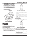
WET CUTTING (GASOLINE ONLY)
To connect the
mechanical water pump
to the drive V-belts
perform the following:
1. Loosen the 2 hex head cap screws (Figure 16) that secure
the pump mount bracket.
2.
Push
the pump handle
downward
to engage the pump.
3. Tighten the 2 hex head cap screws that secure the pump
mount bracket.
Figure 15. Pump Disengage
Figure 16. Pump Engage
NOTE